
Injection molding is one of the most efficient and scalable manufacturing processes for producing plastic parts. However, even the most advanced molding equipment and high-quality materials cannot compensate for poor part design.
Many production issues—such as warpage, sink marks, short shots, and high tooling costs—can be traced back to common injection molding design mistakes made early in the product development stage.
This comprehensive guide explores the most frequent injection molding design errors, explains why they occur, and provides practical solutions to help designers, engineers, and manufacturers avoid costly rework and production delays.
Why Injection Molding Design Matters
Injection molding is a design-driven process. Decisions made during part design directly affect:
- Mold complexity and cost
- Cycle time and production efficiency
- Part strength and durability
- Surface finish and appearance
- Long-term dimensional stability
Poor design choices often lead to expensive mold modifications, longer lead times, and inconsistent part quality. Designing for manufacturability (DFM) from the start is essential for successful injection molding.
Mistake #1: Inconsistent Wall Thickness
Why It’s a Problem
One of the most common injection molding design mistakes is non-uniform wall thickness. Thick and thin sections cool at different rates, causing internal stress, warpage, sink marks, and voids.
Common Issues Caused
- Warping and deformation
- Sink marks over thick sections
- Internal voids
- Longer cooling times
Best Practices
- Maintain uniform wall thickness wherever possible
- Gradually transition between different thicknesses
- Core out thick sections instead of making solid walls
Typical wall thickness ranges:
- Small precision parts: 0.8–1.5 mm
- General plastic parts: 1.5–3.0 mm

Mistake #2: Insufficient Draft Angles
Why It’s a Problem
Draft angles allow molded parts to be ejected smoothly from the mold. Without an adequate draft, parts may stick, deform, or suffer surface damage during ejection.
Common Issues Caused
- Ejection marks
- Scratches and surface defects
- Increased tool wear
- Longer cycle times
Best Practices
- Apply the draft on all vertical surfaces
- Minimum recommended draft:
- 1° per side for smooth surfaces
- 2–3° for textured surfaces
- Increase draft for deep cavities
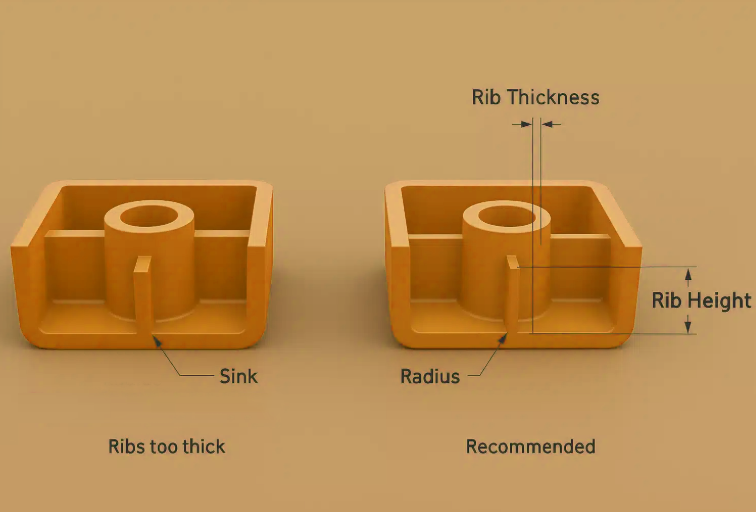
Mistake #3: Poor Rib Design
Why It’s a Problem
Ribs are used to add strength without increasing wall thickness, but poorly designed ribs can create stress concentrations and cosmetic defects.
Common Rib Design Errors
- Ribs that are too thick
- Sharp corners at rib bases
- Ribs are placed too close together
Best Practices
- Rib thickness should be 50–60% of the nominal wall thickness
- Add fillets at the rib bases
- Maintain adequate spacing between ribs
Proper rib design improves stiffness without causing sink marks.
Mistake #4: Ignoring Material Shrinkage
Why It’s a Problem
All plastics shrink as they cool. Failing to account for material shrinkage during design leads to dimensional inaccuracies and assembly problems.
Common Issues Caused
- Parts are out of tolerance
- Assembly misalignment
- Inconsistent dimensions across batches
Best Practices
- Understand the shrinkage rates for the selected resin
- Design parts with appropriate tolerances
- Work closely with mold designers to adjust cavity dimensions
Different materials have different shrinkage characteristics, especially semi-crystalline plastics like PP and nylon.
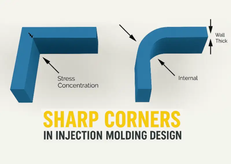
Mistake #5: Sharp Corners and Edges
Why It’s a Problem
Sharp corners concentrate stress and restrict material flow during molding, increasing the risk of cracking and short shots.
Common Issues Caused
- Stress cracking
- Reduced part strength
- Mold filling problems
Best Practices
- Use fillets and radii on all internal and external corners
- Recommended radius: at least 0.5 times the wall thickness
- Larger radii improve flow and reduce stress
Rounded corners also extend mold life and improve part durability.
Mistake #6: Poor Gate Location Selection
Why It’s a Problem
Gate location affects material flow, pressure distribution, and part appearance. Poor gate placement can cause uneven filling and cosmetic defects.
Common Issues Caused
- Weld lines
- Flow marks
- Air traps
- Visible gate scars
Best Practices
- Position gates in thicker sections
- Avoid gating into thin or cosmetic surfaces
- Use simulation tools like mold flow analysis
Gate design should balance aesthetics, strength, and manufacturability.
Mistake #7: Over-Complex Part Geometry
Why It’s a Problem
Complex geometries increase tooling cost, risk of defects, and production time. Features like deep undercuts, thin walls, and sharp transitions complicate mold design.
Common Issues Caused
- Higher tooling costs
- Longer mold lead times
- Increased defect rates
Best Practices
- Simplify geometry where possible
- Minimise undercuts
- Consider part consolidation or modular designs
Design simplicity improves reliability and cost efficiency.
Mistake #8: Neglecting Tolerances
Why It’s a Problem
Overly tight tolerances increase manufacturing difficulty and cost. Plastic parts naturally vary due to material behaviour and process conditions.
Common Issues Caused
- High scrap rates
- Increased inspection costs
- Frequent mold adjustments
Best Practices
- Apply tight tolerances only where functionally necessary
- Allow looser tolerances for non-critical features
- Understand realistic tolerance limits for injection molding
Proper tolerance design balances performance and cost.
Mistake #9: Inadequate Venting Consideration
Why It’s a Problem
Trapped air in the mold prevents complete filling and causes burn marks or short shots.
Common Issues Caused
- Burn marks
- Incomplete filling
- Surface defects
Best Practices
- Design parts with venting in mind
- Avoid blind pockets and dead ends
- Ensure proper vent locations during mold design
Good venting improves part quality and process stability.
Mistake #10: Incorrect Boss Design
Why It’s a Problem
Bosses are often used for fasteners, but improper boss design leads to cracking, sink marks, and weak joints.
Common Boss Design Errors
- Thick boss walls
- Bosses too close to the part edges
- No supporting ribs
Best Practices
- Boss wall thickness: 60% of nominal wall thickness
- Add gussets or ribs for support
- Keep an adequate distance from the edges
Proper boss design improves strength and reduces cosmetic defects.
Mistake #11: Ignoring Assembly and End-Use Conditions
Why It’s a Problem
Designing a part without considering assembly methods and real-world use leads to functional failures.
Common Issues Caused
- Poor snap-fit performance
- Weak fastening points
- Premature part failure
Best Practices
- Design for assembly (DFA)
- Consider load direction, temperature, and environmental exposure
- Validate designs through testing
Understanding how a part is used is critical for long-term performance.
Mistake #12: Not Consulting Injection Molding Experts Early
Why It’s a Problem
Many design flaws occur because molding expertise is introduced too late in the development process.
Common Issues Caused
- Expensive mold revisions
- Delayed production
- Increased costs
Best Practices
- Engage injection molding manufacturers early
- Conduct DFM and mold flow analysis
- Iterate designs before tooling
Early collaboration saves time and money.
How to Avoid Injection Molding Design Mistakes
Avoiding design mistakes in injection molding starts with a strong engineering mindset and early collaboration between designers and manufacturers. Many production issues can be prevented by addressing manufacturability, material behavior, and tooling constraints at the design stage.
Adopt Design for Manufacturability (DFM)
Design for Manufacturability ensures that parts are optimised for efficient molding, reliable quality, and cost-effective production. By applying DFM principles early, designers can reduce unnecessary complexity, ensure uniform wall thickness, improve draft angles, and minimise the risk of defects such as sink marks, warpage, or incomplete filling.
Close communication with the molding supplier during DFM review helps align design intent with real manufacturing conditions.
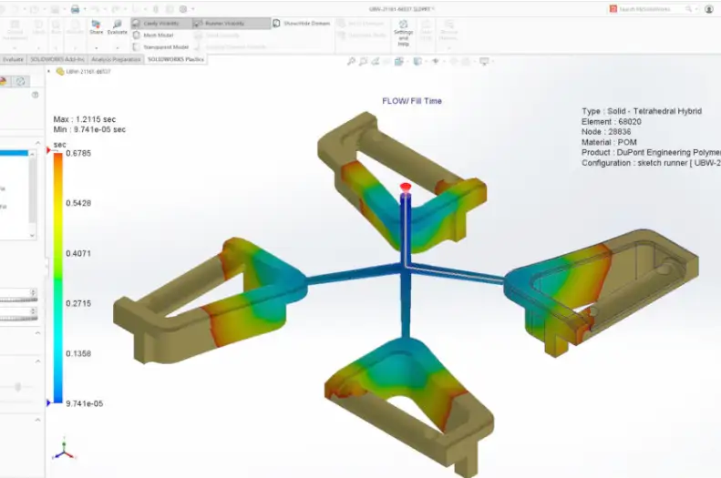
Use Simulation Tools
Mold flow analysis is a powerful tool for identifying potential problems before tooling is built. Simulation software can predict how molten plastic fills the cavity, where weld lines may form, how the part cools, and where warpage or stress concentrations might occur. Using simulation early reduces trial-and-error, shortens development time, and lowers tooling modification costs.
Select the Right Material Early
Material choice directly affects part performance and mold design. Properties such as shrinkage, stiffness, flow behaviour, and heat resistance influence wall thickness, tolerances, and processing parameters. Early material selection ensures consistent results and avoids costly redesigns.
Prototype and Test
Prototyping allows teams to verify design assumptions, evaluate functionality, and identify potential issues before committing to full-scale production, reducing risk and improving final product quality.
Injection Molding Design Checklist
- Uniform wall thickness
- Adequate draft angles
- Proper rib and boss design
- Rounded corners and fillets
- Correct gate placement
- Realistic tolerances
- Consideration of shrinkage
- Good venting strategy
Using a checklist helps catch design errors early.
Conclusion
Avoiding common injection molding design mistakes is essential for producing high-quality plastic parts efficiently and cost-effectively. Poor design choices can result in defects, high tooling costs, and production delays, while well-optimised designs lead to faster cycles, better quality, and long-term success.
By understanding material behaviour, applying proven design guidelines, and collaborating with experienced injection molding professionals, designers can eliminate costly mistakes and ensure reliable, scalable production.
Injection molding success begins with smart design—and avoiding these common mistakes is the first step.