

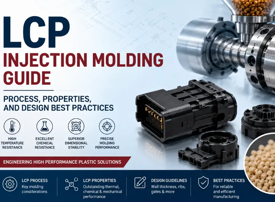
Everything engineers, product developers, and sourcing teams need to know about LCP injection molding — from resin chemistry and flow behavior to gate design, processing windows, defect prevention, and how liquid crystal polymer compares to other high-performance engineering plastics.
Liquid crystal polymer is one of the more demanding materials an injection molder will ever run, and it is also one of the most rewarding when the process is dialed in correctly. Parts that would be impossible to hold to tolerance in nylon or PBT — micro-connectors with wall sections under 0.15 mm, surface-mount components that must survive a 260°C reflow oven without warping, RF antenna housings that need dimensional stability across a wide temperature range — are routine work for LCP once the mold design, the processing parameters, and the material grade selection are aligned.
The problem is that LCP does not forgive the assumptions that work for conventional thermoplastics. Its molecular structure — rigid, rod-like chains that align in the direction of flow — produces mechanical properties that are highly anisotropic, a shrinkage behavior that runs in opposite directions along and across the flow path, and a weld line strength that can drop to a fraction of the base material if the gating is wrong. Molders who treat LCP like an exotic version of nylon or PPS consistently produce parts with warpage, weld line failure, or dimensional variation that never gets resolved through process tweaking alone — because the root cause is upstream in the mold design.
This guide walks through what LCP is and why it behaves the way it does, the material properties that actually matter for part design, the processing window required to mold it successfully, how mold design must change to accommodate its flow behavior, the defects that show up when any of these variables are wrong, where LCP is used in production today, and how it stacks up against the other high-performance resins buyers most often compare it to.
What Is LCP and Why Is It Used in Injection Molding?
Liquid crystal polymer, commonly abbreviated LCP, is a class of aromatic polyester (and in some grades, polyester-amide) engineering thermoplastic whose rigid, rod-shaped molecular chains form ordered, liquid-crystalline domains both in the melt phase and in the solid state. This ordering is what gives LCP its defining characteristics — extremely high strength and stiffness relative to its weight, exceptional dimensional stability at elevated temperature, very low melt viscosity that allows it to fill extraordinarily thin sections, and inherent flame retardancy without the need for halogenated additives in many grades.
LCP is used in injection molding specifically because its combination of properties cannot be matched by conventional engineering resins in the applications where it is specified. Electronics manufacturers rely on LCP for surface-mount connectors and sockets that must survive lead-free reflow soldering at 250–260°C without softening or warping — a temperature that would deform most other thermoplastics. RF and telecom manufacturers use LCP for antenna housings and 5G components because its low dielectric constant and low dissipation factor remain stable across frequency and temperature. Medical device manufacturers use LCP for surgical instrument components and micro-fluidic parts where dimensional precision at sub-millimeter wall sections is a functional requirement, not a cosmetic preference.
The molecular ordering that produces these advantages is also the source of every processing challenge covered later in this guide. Because the rigid chains align with the direction of melt flow rather than randomly orienting like a conventional polymer, LCP parts develop mechanical, thermal, and shrinkage properties that differ substantially between the flow direction and the cross-flow direction. Every design and processing decision covered in this guide exists to manage that anisotropy rather than fight it.
What Are the Key Material Properties of LCP Injection Molding Grades?
LCP is not a single material — it is a family of grades that vary significantly in reinforcement level, flow characteristics, and target application. Understanding the property range across common commercial grades is the starting point for any part design or process development effort, because the differences between an unfilled grade and a 30% glass-filled grade are large enough to change gate location, wall thickness targets, and even mold steel selection.
Typical Property Ranges for Commercial LCP Injection Molding Grades
| Property | Unfilled / Low-Fill LCP | 30% Glass-Filled LCP | Mineral/Glass Hybrid LCP |
|---|---|---|---|
| Tensile strength (flow direction) | 120–160 MPa | 150–200 MPa | 110–150 MPa |
| Tensile strength (cross-flow) | 40–70 MPa | 50–90 MPa | 45–80 MPa |
| Flexural modulus | 8–10 GPa | 12–16 GPa | 10–14 GPa |
| Heat deflection temperature (1.8 MPa) | 190–230°C | 230–260°C | 220–250°C |
| Mold shrinkage (flow direction) | 0.0%–0.2% | 0.0%–0.1% | 0.0%–0.15% |
| Mold shrinkage (cross-flow direction) | 0.6%–1.5% | 0.5%–1.2% | 0.5%–1.3% |
| Melting point range | 280–350°C | 280–350°C | 280–350°C |
| Dielectric constant (1 MHz) | 2.9–3.2 | 3.4–3.9 | 3.6–4.2 |
The shrinkage figures in this table are the single most important number for a part designer to understand before laying out a design, because the gap between flow-direction and cross-flow shrinkage — often a factor of five to ten — is far wider than in any conventional thermoplastic, including other reinforced engineering resins. A part that is dimensionally correct along the direction the melt traveled can be measurably undersized or oversized across that direction on the same cavity, which is why cavity compensation for LCP has to be calculated directionally rather than as a single average shrinkage value.
Tip: Never apply a single average shrinkage value to an LCP cavity. Build the tool with directional shrinkage compensation based on predicted flow paths from mold flow simulation, and verify actual shrinkage with first-article CMM data on both the flow-direction and cross-flow-direction dimensions before releasing the tool for production.
Reinforcement level also changes electrical performance, which matters for the RF and 5G applications where LCP is increasingly specified. Unfilled and low-fill grades generally offer the lowest and most stable dielectric constant, which is why antenna and high-frequency connector applications tend to specify these grades even though they sacrifice some of the stiffness gains that glass-filled grades provide. Selecting the reinforcement level requires balancing mechanical requirements against electrical requirements rather than defaulting to the highest available glass loading.
What Makes LCP Injection Molding Different From Standard Thermoplastic Processing?
LCP injection molding differs from standard thermoplastic processing because the polymer’s molecular chains do not randomly orient during flow the way conventional polymer chains do — they align with the flow front, and that alignment is locked in as soon as the melt cools below its transition temperature. This single structural fact is the root cause of nearly every distinct characteristic of LCP processing: the anisotropic mechanical properties, the directional shrinkage described above, the weld line weakness, and the skin-core layering that shows up in a cross-section of a molded LCP part.
Anisotropic Mechanical Properties
Because the rigid polymer chains align with the flow direction, tensile strength measured along the flow direction can be two to three times higher than strength measured perpendicular to it. This is fundamentally different from glass-fiber-reinforced conventional resins, where fiber orientation contributes to but does not solely determine the anisotropy — in LCP, the base polymer itself is anisotropic even without any reinforcement. Part designers who assume LCP behaves like a stiffer version of an isotropic resin will systematically over-predict strength in the cross-flow direction and under-predict it in the flow direction, which has real consequences for load-bearing features like snap fits, latches, and mounting bosses.
Weld Line Weakness
When two melt fronts meet during mold filling — around a hole, at the convergence point behind an obstruction, or where two gates’ flow fronts join — the aligned molecular chains from each front meet at an angle rather than fusing into a continuous oriented structure. In conventional thermoplastics, weld lines typically retain 60–90% of the base material’s strength. In LCP, weld line strength can fall to 10–30% of the base material’s flow-direction strength, making weld line location one of the single most consequential decisions in LCP mold and gate design — far more consequential than it is for almost any other engineering resin.
Skin-Core Layering
LCP parts develop a distinct layered structure across the wall thickness: highly oriented skin layers near the mold surface where shear forces are highest, and a less-oriented, more randomly structured core layer in the center of the wall. The proportion of skin to core changes with wall thickness, injection speed, and mold temperature, and it directly affects both mechanical properties and surface appearance. Thinner walls are dominated by skin layer behavior — which is part of why LCP performs so well in very thin sections — while thicker walls develop a more substantial core that behaves closer to an isotropic material.
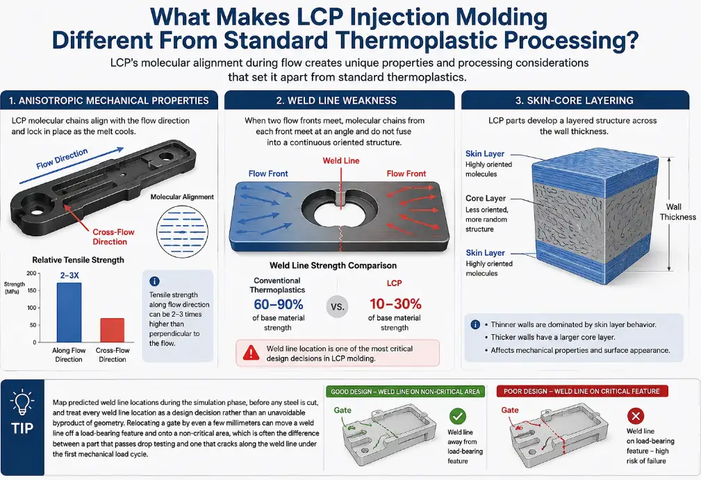
Tip: Map predicted weld line locations during the simulation phase, before any steel is cut, and treat every weld line location as a design decision rather than an unavoidable byproduct of geometry. Relocating a gate by even a few millimeters can move a weld line off a load-bearing feature and onto a non-critical area, which is often the difference between a part that passes drop testing and one that cracks along the weld line under the first mechanical load cycle.
What Processing Parameters Are Required for LCP Injection Molding?
LCP processing windows are narrower and less forgiving than those of conventional engineering thermoplastics, and the parameters that matter most — melt temperature, mold temperature, injection speed, and drying — interact with each other in ways that make LCP a poor candidate for process development by trial and error on the shop floor. Starting from validated parameter ranges and adjusting incrementally against measured part performance is the only reliable approach.
Typical Processing Parameter Ranges for LCP Injection Molding
| Parameter | Typical Range | Processing Notes |
|---|---|---|
| Melt (barrel) temperature | 300–360°C | Grade-dependent; exceeding upper limit risks thermal degradation |
| Mold (tool) temperature | 80–150°C | Higher mold temperatures improve surface finish and crystallinity uniformity |
| Injection speed | Fast to very fast | Low viscosity fills thin sections readily; speed affects skin-core ratio |
| Injection pressure | Moderate | Low melt viscosity generally reduces required fill pressure vs. other engineering resins |
| Pre-drying requirement | 120–150°C for 3–4 hours | Most grades are hygroscopic enough to require drying before processing |
| Residual moisture target | <0.02%–0.04% | Excess moisture causes splay, brittleness, and mechanical property loss |
| Screw design | Low compression ratio, general-purpose | Aggressive shear from high-compression screws promotes degradation |
Melt temperature control matters more for LCP than for most engineering resins because the processing window between full melt flow and thermal degradation is comparatively narrow, and LCP’s low viscosity means the material will readily flash into parting lines and vents at temperatures that would still be safely below the flow threshold of a more viscous resin. Mold temperature is equally important but for a different reason — it directly affects the skin-core ratio discussed earlier, and running a mold too cold produces a thicker, more brittle skin layer with reduced weld line and overall impact performance.
Why Drying Cannot Be Skipped
Most commercial LCP grades absorb enough atmospheric moisture to require pre-drying before molding, even though LCP is sometimes described as having lower moisture sensitivity than nylon. Molding LCP with residual moisture above the target range produces visible splay on the part surface, a measurable drop in mechanical properties from hydrolytic degradation during processing, and — in severe cases — brittleness that shows up only after the part has been in service for a period of time rather than immediately in inspection. Because LCP parts frequently end up in applications where field failure is expensive to diagnose and remediate, skipping or shortcutting the drying step is a false economy that shows up much later in the product lifecycle than it does on the production floor.
Tip: Verify actual resin moisture content with a moisture analyzer rather than relying on drying time alone, particularly after a material has been stored in an open container or in a humid production environment. Dryer set points and dwell times are a starting recommendation, not a guarantee — ambient humidity, hopper loading practices, and dryer maintenance all affect whether the target moisture content is actually being achieved.
How Should Mold Design Change for LCP Parts?
Mold design for LCP has to be approached differently from mold design for conventional engineering thermoplastics because the anisotropic flow behavior, weld line sensitivity, and directional shrinkage described earlier all trace back to decisions made in the gate location, runner layout, wall thickness distribution, and venting design. A mold that would perform well for glass-filled nylon or PBT will frequently produce warped, weak, or dimensionally inconsistent parts if the same layout logic is applied unchanged to LCP.
Gate Location and Type
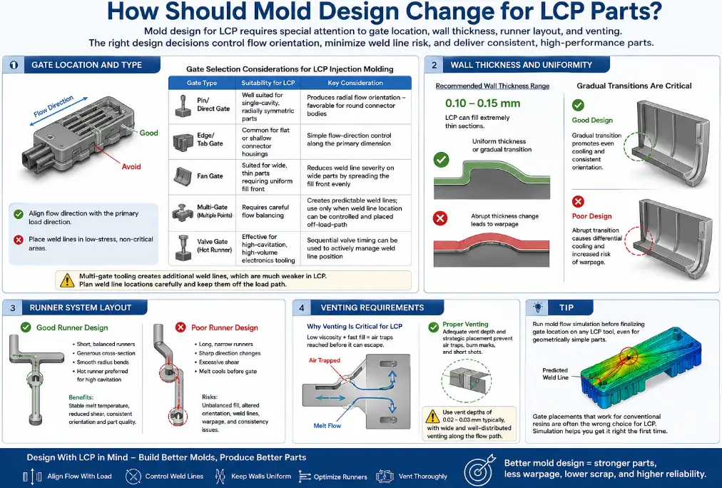
Gate location for LCP parts should be selected to align the predicted flow-direction orientation with the direction of the part’s primary mechanical load, because the flow-direction strength advantage is large enough to be treated as a structural design lever rather than an incidental property. Gate location should also be selected to push any unavoidable weld lines into the lowest-stress regions of the part geometry, given how severely weld line strength degrades in this material.
Gate Selection Considerations for LCP Injection Molding
| Gate Type | Suitability for LCP | Key Consideration |
|---|---|---|
| Pin/direct gate | Well suited for single-cavity, radially symmetric parts | Produces radial flow orientation — favorable for round connector bodies |
| Edge/tab gate | Common for flat or shallow connector housings | Simple flow-direction control along the primary dimension |
| Fan gate | Suited for wide, thin parts requiring uniform fill front | Reduces weld line severity on wide parts by spreading the fill front evenly |
| Multi-gate (multiple points) | Requires careful flow balancing | Creates predictable weld lines; use only when weld line location can be controlled and placed off-load-path |
| Valve gate (hot runner) | Effective for high-cavitation, high-volume electronics tooling | Sequential valve timing can be used to actively manage weld line position |
Multi-gate tooling deserves particular caution with LCP. In conventional resins, adding a second gate to fill a large or complex part is a routine way to reduce fill pressure and balance flow. In LCP, every additional gate creates an additional weld line, and because weld lines are so much weaker in this material than in conventional resins, multi-gate layouts have to be planned with explicit attention to where the resulting weld lines will land — not simply added wherever fill balance calculations suggest they would help.
Wall Thickness and Uniformity
LCP’s low melt viscosity allows it to fill wall sections as thin as 0.10–0.15 mm, which is one of the material’s signature advantages for micro-connector and thin-wall electronics applications. But this capability comes with a design discipline requirement: wall thickness transitions need to be more gradual than they would for a conventional resin, because abrupt thickness changes create localized differences in cooling rate and orientation that amplify LCP’s already-significant directional shrinkage differential, producing warpage at the transition point.
Runner System Layout
Runner design for LCP tooling has to account for the same orientation effects that drive gate and wall thickness decisions, because the resin’s flow-direction alignment begins forming inside the runner itself, not only after the melt enters the cavity. Runners that are too long, too small in cross-section, or routed through sharp direction changes introduce additional shear and cooling before the melt reaches the gate, which can shift the skin-core balance and alter the orientation pattern the part actually receives.
Hot runner systems are widely used in high-cavitation LCP tooling for electronics production because they keep the melt at a stable, uniform temperature all the way to the gate, reducing the run-to-run variability that a cold runner’s changing thermal history can introduce. Where cold runners are used for cost or material-sensitivity reasons, runner cross-sections should be sized generously enough to avoid unnecessary shear heating, and bends should be as gradual as the tool layout allows.
Venting Requirements
Because LCP’s low viscosity allows it to fill a cavity extremely fast, venting has to be sized and positioned with particular care — inadequate venting on an LCP tool produces burn marks and short shots more readily than it would on a more viscous resin, simply because the fast-advancing melt front reaches trapped air pockets before conventional venting design would predict, based on experience with slower-filling materials.
Tip: Run mold flow simulation before finalizing gate location on any LCP tool, even for parts that seem geometrically simple. The counterintuitive flow-direction and weld-line behavior of LCP means that gate placements which would be obviously correct for a conventional resin are frequently the wrong choice for LCP, and the cost of relocating a gate after the mold is built is dramatically higher than the cost of running the simulation up front.
What Are the Most Common Defects in LCP Injection Molding and How Are They Prevented?
The defects that show up in LCP molding overlap partly with conventional thermoplastic defects but are driven by different root causes, which means the corrective actions that work for a conventional resin frequently do not resolve the same-looking defect in LCP. Diagnosing an LCP defect correctly requires starting from the material’s anisotropic flow behavior rather than defaulting to generic troubleshooting logic.
Common LCP Injection Molding Defects, Root Causes, and Corrective Actions
| Defect | Typical Root Cause in LCP | Corrective Action |
|---|---|---|
| Warpage across thin sections | Directional shrinkage mismatch between flow and cross-flow directions | Rebalance gate location; adjust wall thickness uniformity; apply directional cavity compensation |
| Weld line cracking under load | Severe strength reduction at melt front convergence points | Relocate gate to move weld line off load path; consider valve-gate sequencing |
| Surface splay/silver streaking | Residual moisture in the resin at time of molding | Verify drying with a moisture analyzer; check dryer performance and hopper sealing |
| Delamination/flaking surface layers | Excessive skin-core separation from processing conditions | Increase mold temperature; adjust injection speed profile; review screw shear |
| Flash at parting line or vents | Low melt viscosity flowing into undersized clearances | Tighten parting line fit; review vent depth against LCP-specific vent guidelines |
| Short shots in thin ribs | Premature freeze-off before flow-direction orientation completes | Increase mold temperature locally; increase injection speed; verify venting adequacy |
| Dimensional variation part to part | Inconsistent skin-core ratio from unstable process conditions | Lock process window; monitor melt and mold temperature stability; audit machine repeatability |
Delamination is worth calling out specifically because it is one of the defects most unique to LCP among commonly molded engineering resins. When processing conditions produce an excessively pronounced skin-core structure, the layers can separate under mechanical stress or thermal cycling, appearing as visible flaking or peeling at the part surface — a failure mode that has no direct equivalent in conventional thermoplastic molding and that is frequently misdiagnosed as a material quality issue when the actual root cause is a processing parameter imbalance.
Tip: When troubleshooting an LCP defect, check the mold and melt temperature stability before adjusting anything else. A surprising share of intermittent LCP defects — dimensional drift, inconsistent surface appearance, sporadic weld line failures — trace back to temperature control instability rather than a fundamentally wrong process setpoint, because LCP’s sensitivity to thermal conditions is higher than that of most conventional engineering resins.
Which Industries and Applications Rely on LCP Injection Molded Parts?
LCP’s combination of thin-wall moldability, high-temperature stability, and stable electrical properties has concentrated its commercial use in a relatively focused set of high-value applications rather than the broad general-purpose use seen with resins like ABS or polypropylene. Understanding where LCP is specified helps clarify why its processing challenges are considered worth managing rather than avoided in favor of an easier-to-process alternative.
Primary Industries and Applications for LCP Injection Molded Parts
| Industry | Typical Applications | Key Property Driving Selection |
|---|---|---|
| Electronics and connectors | Surface-mount connectors, sockets, board-to-board connectors | Reflow-soldering temperature resistance; thin-wall moldability |
| Telecommunications / 5G | Antenna housings, RF shielding components, small-cell parts | Low and stable dielectric constant; dimensional stability |
| Medical devices | Surgical instrument components, microfluidic housings | Precision at sub-millimeter wall sections; chemical resistance |
| Automotive electronics | Sensor housings, under-hood connectors | Heat resistance; dimensional stability near engine components |
| Aerospace | Lightweight structural brackets, insulating components | High strength-to-weight ratio; flame retardancy without additives |
| Fiber optics | Ferrules, connector housings | Dimensional precision; low moisture absorption |
Electronics and connector manufacturing remains the largest single volume driver for LCP consumption, largely because of the shift toward lead-free reflow soldering processes across the industry over the past two decades. Lead-free solder reflows at a higher peak temperature than the leaded processes it replaced, and LCP’s heat deflection temperature — comfortably above the reflow peak in most grades — made it one of the few economically viable options for surface-mount plastic components that must go through the oven without deforming.
The telecommunications and 5G segment has grown into the second major volume driver over the past several years, as network equipment manufacturers have needed housings and structural components that maintain consistent electrical performance across a wider range of operating frequencies and temperatures than earlier generations of network hardware required. LCP’s combination of a low, stable dielectric constant and dimensional stability under thermal cycling has made it a standard material choice for small-cell antenna housings and RF connector components in this category, often specified alongside — or in place of — machined metal components where weight and cost pressures favor an injection-molded solution.
Tip: When qualifying LCP for a reflow-soldered application, test the actual molded part through the target reflow profile rather than relying solely on the resin’s published heat deflection temperature. Localized thin sections, weld lines, and molded-in stress can all reduce a specific part’s practical heat resistance below the datasheet value for the base material.
How Does LCP Compare to Other High-Performance Engineering Resins?
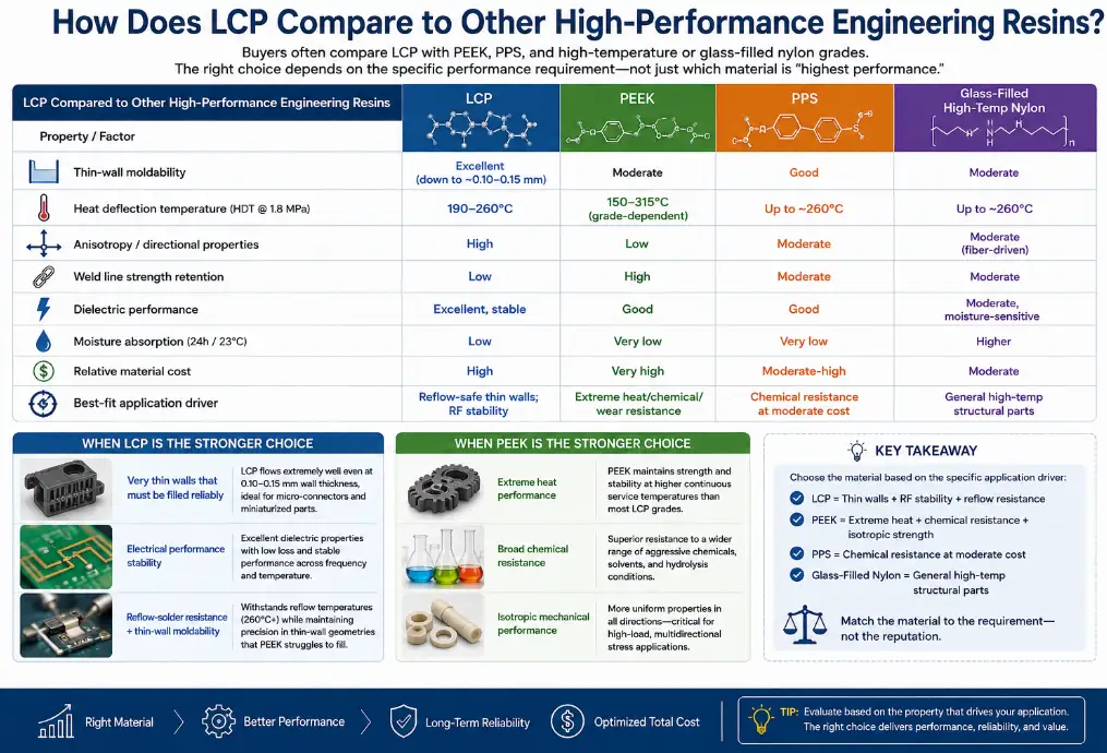
Buyers evaluating LCP for a demanding application are frequently comparing it against PEEK, PPS, and high-temperature or glass-filled nylon grades — resins that occupy an overlapping but distinct performance and cost tier. Choosing correctly between them requires comparing the specific property that is driving the application requirement rather than defaulting to a general perception of which material is “highest performance.”
LCP Compared to Other High-Performance Engineering Resins
| Property / Factor | LCP | PEEK | PPS | Glass-Filled High-Temp Nylon |
|---|---|---|---|---|
| Thin-wall moldability | Excellent (down to ~0.10–0.15 mm) | Moderate | Good | Moderate |
| Heat deflection temperature | 190–260°C | 150–315°C (grade-dependent) | Up to ~260°C | Up to ~260°C |
| Anisotropy / directional properties | High | Low | Moderate | Moderate (fiber-driven) |
| Weld line strength retention | Low | High | Moderate | Moderate |
| Dielectric performance | Excellent, stable | Good | Good | Moderate, moisture-sensitive |
| Moisture absorption | Low | Very low | Very low | Higher |
| Relative material cost | High | Very high | Moderate-high | Moderate |
| Best-fit application driver | Reflow-safe thin walls; RF stability | Extreme heat/chemical/wear resistance | Chemical resistance at moderate cost | General high-temp structural parts |
The comparison against PEEK is the one buyers most often need help resolving, because both materials are positioned at the premium end of the engineering resin market and both are associated with demanding applications. PEEK is the stronger choice when the application requires isotropic mechanical performance, superior chemical resistance across a broad range of aggressive media, or continuous service temperatures beyond what most LCP grades sustain.
LCP is the stronger choice when the part geometry includes very thin walls that must be filled reliably, when electrical performance stability is the primary requirement, or when the specific combination of reflow-solder resistance and thin-wall moldability is the deciding factor — a combination PEEK’s higher viscosity makes more difficult to achieve in the same wall sections.
What Should Buyers Evaluate When Choosing an LCP Injection Molding Partner?
Because LCP’s processing window is narrower and its defect modes are less forgiving than conventional resins, the choice of molding partner has a larger influence on part success than it does for easier-to-process materials. A supplier with deep experience in glass-filled nylon or ABS does not automatically transfer that competence to LCP, and buyers evaluating potential partners should look specifically for evidence of LCP-specific capability rather than general injection molding experience.
Evaluation Criteria for an LCP Injection Molding Partner
| Evaluation Area | What to Look For |
|---|---|
| Mold flow simulation capability | In-house or contracted simulation with documented LCP flow and weld line prediction |
| Directional shrinkage compensation experience | Evidence of prior tools built with flow/cross-flow specific cavity compensation |
| Drying and moisture control infrastructure | Dedicated dryers with monitored setpoints and moisture verification practice |
| Process monitoring and repeatability | Closed-loop or actively monitored melt and mold temperature control |
| Micro-molding / thin-wall tooling experience | Reference parts demonstrating sub-0.2 mm wall sections in production |
| Weld line testing and validation practice | Willingness to share weld line strength test data, not just base material data |
| Material traceability and lot documentation | Full lot traceability and certificate of analysis availability per shipment |
Reference parts are the most direct way to verify a supplier’s actual LCP capability rather than relying on their self-description. Asking a prospective partner to walk through a previous LCP project — the wall thickness achieved, the weld line locations they managed, the shrinkage compensation approach they used, and the defect rate they achieved in production — reveals far more about their real capability than a general capabilities statement or a list of resins they claim to process. Suppliers such as AIM Plastic, which maintain dedicated process documentation and simulation workflows specifically for anisotropic resins like LCP, are generally better positioned to hold tight tolerances on thin-wall, weld-line-sensitive geometries than shops applying general-purpose engineering-resin process logic to a material that does not follow the same rules.
It is also worth asking how a prospective partner handles the transition from prototype to production tooling. Because first-shot dimensions on an LCP part rarely match final production dimensions without at least one round of directional shrinkage correction, a supplier’s process for measuring first-article parts, isolating flow-direction versus cross-flow deviation, and feeding that data back into cavity steel adjustments says a great deal about whether they are equipped to bring an LCP program to a stable, repeatable process — or whether they will treat the first several production runs as an extended trial-and-error period at the buyer’s expense.
Conclusion
LCP injection molding rewards a design and process approach built specifically around the material’s anisotropic flow behavior rather than an approach adapted from conventional thermoplastic experience. The properties that make LCP valuable — thin-wall moldability, reflow-solder heat resistance, stable electrical performance — are inseparable from the properties that make it demanding to process: directional shrinkage, weld line sensitivity, and a narrower thermal processing window than most engineering resins.
The path to a successful LCP part runs through the same sequence at every stage: understand the grade-specific property data rather than treating LCP as a single generic material, simulate flow and weld line behavior before committing to steel, design gate location and wall thickness with directional orientation as a primary consideration rather than an afterthought, control drying and thermal stability tightly during processing, and verify actual part performance — including weld line strength and directional dimensions — rather than relying solely on base material datasheet values.
Buyers and engineers who follow this sequence consistently get the results LCP is capable of delivering: connectors that survive reflow without distortion, antenna housings that hold their electrical performance across temperature, and micro-molded components at wall sections no other engineering resin can reliably fill. The material’s reputation for being difficult to process is accurate only for teams that have not built their workflow around its specific behavior — for those who have, LCP is simply a different, well-understood set of rules rather than an unpredictable one.
FAQ
Q1. Why does LCP shrink differently in the flow direction compared to the cross-flow direction?
LCP shrinks differently in the two directions because its rigid polymer chains align with the direction of melt flow during filling, and that alignment locks in as the part cools. Along the flow direction, the aligned chains resist further contraction, producing very low shrinkage — often close to zero. Perpendicular to the flow direction, there is comparatively little chain alignment resisting contraction, so shrinkage in that direction is substantially higher, frequently five to ten times the flow-direction value. This is a structural consequence of the material’s liquid-crystalline molecular behavior, not a processing defect, and it must be addressed through directional cavity compensation rather than a single average shrinkage factor.
Q2. Can LCP parts be molded with multiple gates without creating weak weld lines?
Multiple gates can be used successfully with LCP, but only when the resulting weld line locations are deliberately planned rather than left to fall wherever flow balance calculations happen to place them. Because weld line strength in LCP can drop to a small fraction of the base material’s flow-direction strength, every additional gate needs to be evaluated for where its weld line will land relative to the part’s load paths. Techniques such as sequential valve gating, which allows the timing of each gate opening to be controlled, give tooling engineers a way to actively manage weld line position rather than accepting it as a fixed consequence of gate count and location.
Q3. What wall thickness range is realistic for LCP injection molding?
LCP’s low melt viscosity allows production wall thicknesses as thin as approximately 0.10–0.15 mm in well-designed, well-gated parts, which is thinner than most conventional engineering thermoplastics can reliably fill. Typical production wall thicknesses for connectors and electronics housings fall in the 0.20–0.80 mm range. Thicker sections above roughly 2–3 mm are possible but are less common in practice, both because LCP is rarely specified for parts that do not need its thin-wall or heat-resistance advantages, and because thicker sections develop a more pronounced core layer that reduces some of the property advantages that justify LCP’s higher material cost in the first place.
Q4. Does LCP need to be dried before every production run, or only after long storage?
Most commercial LCP grades are hygroscopic enough that pre-drying is a standard requirement before every production run, not just after extended storage in an open environment. Even resin drawn from a sealed container can pick up enough ambient moisture during transfer, hopper loading, and dwell time in a humid production environment to exceed the target residual moisture level. Because moisture-related defects — splay, brittleness, reduced mechanical properties — are not always visible at the point of molding and can surface later during part service life, skipping the drying step to save cycle time on a run is a decision that trades a small time saving for a disproportionate quality risk.
Q5. How does LCP’s electrical performance compare across different reinforcement levels?
Unfilled and low-glass-fill LCP grades generally provide the lowest and most stable dielectric constant and dissipation factor, which is why they are typically specified for antenna housings, RF shielding, and other high-frequency applications where electrical stability across temperature and frequency is the primary requirement. Higher glass-fill grades increase stiffness and heat deflection temperature but also raise the dielectric constant and can introduce more variability in electrical performance due to the fiber-glass interface. Selecting reinforcement level for an electrically sensitive application should start from the target dielectric specification rather than defaulting to the highest available glass loading for mechanical margin.
Q6. What causes delamination in LCP molded parts, and how is it different from delamination in other resins?
Delamination in LCP results from an excessively pronounced separation between the highly oriented skin layer and the less-oriented core layer that forms across the part’s wall thickness during molding. When processing conditions — typically a mold temperature that is too low or an injection speed profile that promotes excessive shear at the wall — produce too sharp a distinction between these layers, they can separate under mechanical or thermal stress, appearing as visible flaking or peeling. This failure mode has no close equivalent in conventional thermoplastic molding, where delamination (when it occurs at all) is usually linked to material contamination or incompatible regrind blending rather than the resin’s own molecular orientation behavior.
Q7. Is LCP a good substitute for PEEK in every high-temperature application?
LCP is not a universal substitute for PEEK, and the two materials are better understood as suited to different aspects of high-performance applications rather than as interchangeable options at different price points. LCP outperforms PEEK for very thin-wall geometries and for applications where electrical stability is the primary requirement, and it is significantly easier to process into thin sections due to its lower melt viscosity. PEEK outperforms LCP where isotropic mechanical strength, superior chemical resistance across a broader range of aggressive media, or the highest continuous-use temperatures are the deciding requirement. The correct choice depends on which specific property is driving the application’s failure risk, not on a general ranking of which material is considered higher performance.
Q8. How much more expensive is LCP tooling and processing compared to conventional engineering resins?
LCP resin cost is typically several times higher per kilogram than conventional engineering resins such as nylon or PBT, and tooling for LCP parts often carries a premium reflecting the additional simulation work, directional shrinkage compensation, and tighter tolerance requirements involved in a successful design. Processing costs are influenced less by cycle time — LCP’s low viscosity and fast crystallization frequently allow competitive cycle times — and more by the drying infrastructure, process monitoring, and quality verification steps required to consistently hit the narrower processing window the material demands. Buyers evaluating LCP against a lower-cost alternative should weigh these costs against the application requirements that specifically justify LCP, rather than treating the cost premium as a reason to default to a less capable material for a demanding application.