
Design for Manufacturability (DFM) is one of the most important—and most misunderstood—concepts in plastic injection molding.
Many product designs look perfect in CAD. They pass internal reviews, meet functional requirements, and even look great in renders. But once they reach the mold shop, problems start to appear: tooling costs explode, lead times stretch, parts warp, sink, or crack, and production becomes unstable.
Most of these issues don’t come from poor molding. They come from designs that were never optimized for manufacturing.
This article breaks down DFM for plastic injection molding from a real-world manufacturing perspective. No theory-only talk. Just practical rules, examples, and decision-making logic used by experienced mold designers and injection molding engineers.
What Is Design for Manufacturability (DFM)?
Design for Manufacturability (DFM) is the practice of designing plastic parts so they can be produced consistently, efficiently, and at the lowest possible cost—without sacrificing function or quality.
In injection molding, DFM focuses on:
- Tooling feasibility
- Material behavior
- Process stability
- Cycle time optimization
- Defect prevention
- Long-term production reliability
Good DFM means the part works not only on the screen, but on the production floor.
Why DFM Matters in Plastic Injection Molding
Ignoring DFM almost always leads to:
- Expensive mold modifications
- Long trial-and-error cycles
- High scrap rates
- Unstable dimensions
- Missed launch deadlines
Proper DFM, on the other hand:
- Reduces mold cost
- Shortens lead time
- Improves part consistency
- Extends mold life
- Lowers per-part cost
In high-volume injection molding, small design mistakes multiply fast. A 0.5 mm design change can mean tens of thousands of dollars in tooling and production loss.
DFM Starts Before Mold Design
One common mistake is thinking DFM begins after the CAD design is finished. In reality, DFM should start before the first mold layout.
Key early-stage questions:
- Is injection molding the right process?
- Is the target annual volume realistic?
- Is the selected material mold-friendly?
- Are tolerances truly necessary?
Answering these early questions saves time and money later.
Material Selection and DFM Considerations
Material choice directly affects manufacturability.
Key Material Factors
When selecting a plastic material, consider:
- Flow characteristics
- Shrinkage rate
- Warpage tendency
- Moisture sensitivity
- Mold temperature requirements
Common Material DFM Notes
Polypropylene (PP)
- Easy to mold
- High shrinkage
- Needs proper rib and wall design
ABS
- Good dimensional stability
- Sensitive to shear and stress
- Benefits from larger gates
Nylon (PA)
- Strong and heat-resistant
- High moisture absorption
- Requires drying and larger gates
Glass-Filled Plastics
- Higher strength
- Directional shrinkage
- Increased tool wear
DFM means choosing materials that meet both functional and manufacturing needs, not just mechanical specs.

Uniform Wall Thickness: The Foundation of DFM
If there is one golden rule in injection molding DFM, it’s this:
Keep wall thickness as uniform as possible.
Why Uniform Wall Thickness Matters
Non-uniform walls cause:
- Sink marks
- Internal voids
- Warpage
- Uneven cooling
- Long cycle times
Thicker sections cool more slowly and shrink more. This imbalance creates internal stress and visible defects. Practical Wall Thickness Guidelines
- Avoid sudden thickness changes
- Use gradual transitions (tapers or steps)
- Core out thick sections instead of making them solid
Typical wall thickness ranges:
- Small parts: 1.0–2.0 mm
- Medium parts: 2.0–3.0 mm
- Large structural parts: 3.0–4.0 mm
Thicker is rarely better.
Draft Angles: Essential for Easy Ejection
Draft angles allow parts to release smoothly from the mold.
Why Draft Is Non-Negotiable
Without an adequate draft:
- Parts stick to the mold
- Ejection forces increase
- Surface damage occurs
- Cycle time increases
Recommended Draft Angles
- Smooth surfaces: ≥ 1°
- Textured surfaces: 2°–5°
- Deep ribs or bosses: more draft required
A common mistake is designing “zero-draft” walls for aesthetic reasons. In production, this almost always causes problems.
Rib Design: Strength Without Thickness
Ribs are used to add stiffness without increasing wall thickness—but only when designed correctly.
Rib Design Rules
- Rib thickness: 50–60% of nominal wall
- Rib height: ≤ 3× wall thickness
- Add draft (0.5°–1° minimum)
- Use fillets at rib bases
Common Rib Mistakes
- Ribs too thick → sink marks
- Sharp corners → stress concentration
- No draft → ejection issues
Proper rib design is a classic DFM win: stronger parts with better moldability.
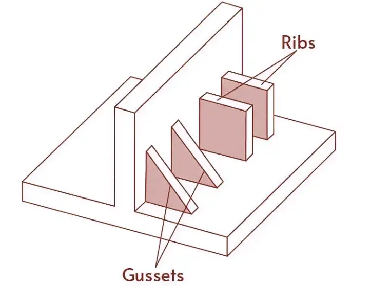
Boss Design for Screws and Fasteners
Bosses are critical functional features—and frequent defect sources.
Boss Design Best Practices
- Boss wall thickness ≤ 60% of nominal wall
- Use gussets instead of thick walls
- Avoid placing bosses on cosmetic surfaces
- Add generous fillets at the base
Boss Placement Tips
- Keep bosses away from part edges
- Avoid clustering multiple bosses too closely
- Support tall bosses with ribs
Well-designed bosses reduce cracking, sink marks, and assembly failures.
Undercuts and Side Actions: Use Carefully
Undercuts complicate mold design and increase cost.
DFM Considerations for Undercuts
Undercuts often require:
- Side actions
- Lifters
- Collapsible cores
These add:
- Tooling cost
- Mold complexity
- Maintenance risk
DFM Rule of Thumb
If an undercut is not functionally necessary, remove it.
If it is necessary:
- Minimize depth
- Ensure proper draft
- Confirm mold movement early
Simple molds are more reliable and cheaper to run.
Hole Design and Coring Strategy
Holes should be designed with moldability in mind.
Hole DFM Guidelines
- Core holes instead of drilling when possible
- Hole depth ≤ 3× diameter
- Maintain consistent wall thickness around holes
Deep, thin core pins are fragile and prone to breakage. DFM balances part requirements with tool durability.
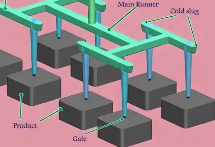
Gate Design and Placement in DFM
Gate design is tightly linked to manufacturability.
DFM Gate Objectives
- Short flow paths
- Balanced filling
- Proper packing
- Clean gate break
Common DFM Gate Mistakes
- Gating into thin sections
- Gating onto cosmetic surfaces
- Gates that freeze too early
Gate location should always be reviewed during the DFM stage, not after tooling begins.
Tolerances: Be Realistic
Overly tight tolerances are a major cost driver.
Injection Molding Reality
Plastic parts:
- Shrink
- Warp
- React to temperature and humidity
DFM Tolerance Guidelines
- Apply tight tolerances only where functionally required
- Use datum-based tolerancing
- Avoid stacking tight tolerances
Relaxed tolerances = lower cost and higher yield.
Surface Finish and Texture Considerations
Surface requirements affect mold design and cost.
DFM Surface Finish Tips
- High-gloss finishes require better steel and polishing
- Textures require additional draft
- Mixed finishes complicate mold processing
If appearance is not critical, don’t over-specify surface finish.
Ejection System and DFM
Parts must eject reliably.
Ejection DFM Rules
- Provide flat ejection areas
- Avoid thin, fragile features near ejector pins
- Use ribs and bosses as ejection support
Poor ejection design leads to part damage and production delays.
Cooling Design and DFM
Cooling dominates cycle time.
DFM Cooling Principles
- Uniform wall thickness improves cooling
- Avoid thick mass areas
- Design parts that allow close cooling channels
Good DFM = faster cycles and lower unit cost.
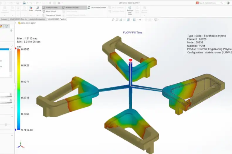
Mold Flow Analysis and DFM
Modern DFM relies on simulation.
Mold flow helps:
- Validate wall thickness
- Optimize gate location
- Predict weld lines
- Reduce warpage risk
DFM decisions backed by simulation reduce trial-and-error.
Common DFM Mistakes to Avoid
- Designing for appearance only
- Ignoring draft angles
- Overusing undercuts
- Over-tight tolerances
- Late DFM reviews
Most injection molding failures are design failures, not process failures.
DFM Review Checklist for Injection Molding
Before finalizing a design, confirm:
- Uniform wall thickness
- Adequate draft everywhere
- Ribs and bosses are properly sized
- Minimal undercuts
- Realistic tolerances
- Gate locations reviewed
- Ejection considered
If the part passes this checklist, it’s likely production-ready.
Final Thoughts: DFM Is a Competitive Advantage
Design for Manufacturability in plastic injection molding is not about limiting creativity. It’s about designing smarter.
Companies that embrace DFM:
- Launch faster
- Spend less on tooling
- Achieve higher quality
- Scale production with confidence
A part designed with DFM in mind doesn’t just work—it manufactures smoothly, consistently, and profitably.
If you want injection molding success, start with DFM—not after problems appear, but before the mold is ever cut.