
Gate design and placement play a critical role in the success of any injection molding project. Even with a perfectly designed part and a high-precision mold, poor gate selection can lead to cosmetic defects, weak weld lines, warpage, sink marks, and unstable production cycles.
In real-world injection molding, many quality issues trace back not to material or machine settings, but to incorrect gate type, size, or location.
This guide breaks down gate design and placement from a practical, production-focused perspective—not theory alone. Whether you’re designing molds, reviewing DFM feedback, or troubleshooting molding defects, this article will help you make smarter decisions.
What Is a Gate in Injection Molding?
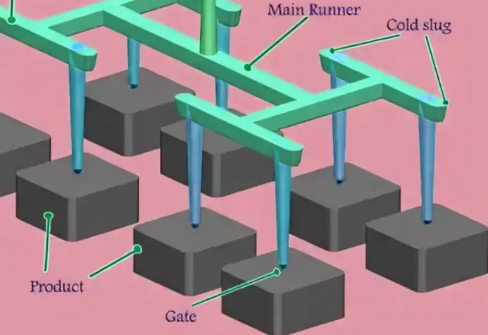
In injection molding, a gate is the narrow opening that connects the runner system to the mold cavity. It controls how molten plastic enters the cavity and determines:
- Flow direction
- Filling speed
- Packing efficiency
- Cooling behavior
- Gate vestige appearance
Think of the gate as a valve—it regulates how material fills the part and when the cavity seals off during packing and cooling.
Why Gate Design Matters
A poorly designed gate can cause:
- Short shots
- Flow hesitation
- Excessive shear stress
- Jetting and burn marks
- Weak mechanical performance
- Visible gate marks on cosmetic surfaces
A well-designed gate, on the other hand:
- Ensures balanced filling
- Improves surface finish
- Enhances part strength
- Reduces cycle time
- Improves mold longevity
Gate design is not optional optimization—it’s fundamental engineering.
Key Functions of the Gate
Before diving into types and placement, it’s important to understand what a gate must do.
1. Control Melt Flow
The gate controls how fast molten plastic enters the cavity. Too small → high shear, burn marks. Too large → poor gate break and cosmetic issues.
2. Enable Effective Packing
During the packing phase, the gate must remain open long enough to compensate for material shrinkage.
If the gate freezes too early:
- Sink marks appear
- Internal voids form
- Dimensional stability suffers
3. Separate the Part Cleanly
After molding, the gate should break cleanly from the part with minimal vestige, especially for visible or functional surfaces.
Common Types of Gate Design and Placement
Different applications require different gate types. There is no “best” gate—only the right gate for the part.
1. Edge Gate
Description:
Material enters the cavity from the edge of the part.
Advantages:
- Simple design
- Easy to machine
- Reliable filling
- Suitable for most thermoplastics
Disadvantages:
- Visible gate mark
- May cause flow imbalance in large parts
Best for:
- Flat or plate-like parts
- Medium to large components
- Non-cosmetic edges
2. Tab Gate
Description:
A variation of the edge gate with a thicker tab before the part.
Advantages:
- Reduces shear stress
- Improves flow into thin sections
- Minimizes gate blush
Disadvantages:
- Extra material needs trimming
Best for:
- Brittle materials (ABS, PMMA)
- Parts sensitive to flow marks

3. Fan Gate
Description:
The gate gradually widens like a fan to distribute the flow evenly.
Advantages:
- Uniform filling
- Reduced weld lines
- Lower internal stress
Disadvantages:
- Larger gate vestige
- More complex tooling
Best for:
- Large flat parts
- Cosmetic panels
- Thin-wall components
4. Submarine (Tunnel) Gate
Description:
The gate enters below the parting line and breaks automatically during ejection.
Advantages:
- Automatic degating
- Clean appearance
- High production efficiency
Disadvantages:
- Limited gate size
- Higher shear stress
- More difficult to machine
Best for:
- High-volume production
- Small to medium parts
- Hidden gate locations
5. Pin Gate (Hot Runner)
Description:
Direct gate from a hot runner nozzle into the part.
Advantages:
- No runner waste
- Excellent packing
- Short cycle times
Disadvantages:
- Visible gate mark
- Higher tooling cost
Best for:
- High-precision parts
- High-volume production
- Multi-cavity molds
6. Valve Gate
Description:
A controlled hot runner gate with a mechanical pin.
Advantages:
- Precise flow control
- Excellent cosmetic quality
- No stringing or drooling
Disadvantages:
- Very high mold cost
- Complex maintenance
Best for:
- Automotive interiors
- Medical and cosmetic housings
- Premium surface finishes
Gate Size Design: Practical Guidelines
Gate size directly affects filling pressure, shear rate, and gate freeze time.
Key Principles
- Too small:
- High shear stress
- Burn marks
- Premature gate freeze
- Too large:
- Difficult degating
- Poor appearance
- Over-packing risk
General Gate Thickness Rules
A common rule of thumb:
Gate thickness = 50–80% of nominal wall thickness
Examples:
- Wall thickness 2.0 mm → gate thickness 1.0–1.6 mm
- Wall thickness 3.0 mm → gate thickness 1.5–2.4 mm
Gate Width Considerations
- Wider gates reduce shear
- Narrow gates increase shear and pressure
- Fan or tab gates help spread flow without increasing thickness
Gate size should always be verified with mold flow analysis, especially for:
- Thin-wall parts
- Glass-filled materials
- Long flow lengths
Gate Placement: Where Most Problems Begin
Gate placement determines how the part fills, cools, and shrinks in the injection molds.

Core Objectives of Good Gate Placement
- Short, balanced flow paths
- Uniform packing pressure
- Controlled weld line locations
- Minimal warpage
Place Gates at Thick Sections
Always gate into the thickest section of the part whenever possible.
Why?
- Thick areas cool more slowly
- Better packing compensation
- Reduced sink and voids
Gating into thin sections often causes:
- Short shots
- Flow hesitation
- High injection pressure
Avoid Gating into Cosmetic or Functional Surfaces
Gate marks are almost always visible.
Avoid:
- Front-facing surfaces
- Textured or glossy areas
- Sealing surfaces
- Snap-fit regions
Preferred locations:
- Hidden edges
- Back sides
- Internal ribs
- Non-functional flanges
Control Weld Line Locations
When multiple flow fronts meet, weld lines form.
Poor gate placement can cause weld lines at:
- Load-bearing areas
- Snap hooks
- Screw bosses
Good gate placement:
- Pushes weld lines into low-stress areas
- Aligns weld lines with ribs or corners
For structural parts, this is critical.
Gate Direction Matters
Molten plastic flows like thick syrup—it has memory.
Gate direction affects:
- Fiber orientation (glass-filled plastics)
- Strength anisotropy
- Surface appearance
For glass-filled materials:
- Align flow with load direction when possible
- Avoid abrupt flow turns near critical features
Single Gate vs Multiple Gates
Single Gate Designs
Pros:
- Simple mold design
- Lower tooling cost
- Fewer weld lines
Cons:
- Longer flow lengths
- Higher pressure
- Risk of imbalance in large parts
Best for:
- Small to medium parts
- Simple geometries
Multiple Gate Designs
Pros:
- Shorter flow paths
- Lower pressure
- Better filling of large parts
Cons:
- Weld lines
- Flow balancing challenges
- More complex tooling
Best for:
- Large flat parts
- Symmetrical designs
- Multi-cavity molds
Multiple gates should always be balanced using runner design and mold flow simulation.
Gate Design for Different Materials
Material behavior strongly affects gate performance.
Polypropylene (PP)
- Low viscosity
- Forgiving material
- Works well with small gates
Watch out for:
- Shrinkage
- Sink marks if the gate freezes early
ABS
- Medium viscosity
- Sensitive to shear
Recommendations:
- Use tab or fan gates
- Avoid very small pin gates

Nylon (PA)
- High flow, but moisture sensitive
- High shrinkage
Recommendations:
- Larger gates
- Gate into thick sections
- Maintain packing pressure
Glass-Filled Plastics
- Abrasive
- Directional strength
Recommendations:
- Avoid sharp gate edges
- Optimize flow direction
- Use hardened steel at gate area
Common Gate-Related Defects and Solutions
1. Jetting
Cause:
High-speed flow from a small gate into an open cavity.
Solutions:
- Enlarge gate
- Reduce injection speed
- Change gate angle
2. Sink Marks Near Gate
Cause:
Gate freezes too early.
Solutions:
- Increase gate thickness
- Relocate the gate closer to the thick section
- Increase packing time
3. Gate Blush / Stress Whitening
Cause:
High shear stress at the gate.
Solutions:
- Use tab or fan gate
- Reduce injection speed
- Increase gate size
4. Difficult Degating
Cause:
Gate too large or incorrect type.
Solutions:
- Switch to the tunnel gate
- Reduce gate thickness
- Modify gate angle
Gate Design and Mold Flow Analysis
Modern gate design should not rely on experience alone.
Mold flow simulation helps:
- Predict filling behavior
- Optimize gate location
- Visualize weld lines
- Reduce trial-and-error
For complex parts, mold flow can save:
- Tool modification costs
- Weeks of development time
- Production scrap
Practical Gate Design Checklist
Before finalizing a mold design, ask:
- Is the gate located at the thickest section?
- Is the gate size appropriate for the material?
- Are weld lines in low-stress areas?
- Is the gate hidden from cosmetic surfaces?
- Will the gate freeze after sufficient packing?
- Is degating practical for production volume?
If any answer is “no,” revise the gate.
Final Thoughts: Gate Design Is Not a Detail
In injection molding, gate design and placement are not minor decisions. They influence:
- Part quality
- Mechanical performance
- Production efficiency
- Tooling lifespan
Experienced mold designers know that a well-designed gate often solves problems before they exist.
If you’re facing repeated molding defects, inconsistent quality, or long setup times, look at the gate first—it’s often where the real issue begins.
Smart gate design turns a good injection mold into a great one.