Injection mold design service
We provide injection mold design service with engineering support, competitive price, mold making, CNC machining, 3D printing, post finishing etc

Injection mold design is the technical backbone of reliable plastic injection molding. Regardless of how advanced the molding machine is or how carefully a plastic material is selected, poor mold design will inevitably lead to defects, unstable quality, excessive scrap, and inefficient production cycles. In real-world manufacturing, the mold directly controls how a plastic part is formed, cooled, and ejected, making injection mold design a decisive factor in overall product success.
A well-engineered injection mold ensures consistent plastic flow, controlled cooling, and precise dimensional accuracy throughout the injection molding process. From part design and gate location to cooling layout and ejection strategy, every detail of injection molding tool design influences the quality and performance of the final injection molded part. Applying proven plastic mold design principles allows manufacturers to avoid common issues such as warpage, sink marks, short shots, and premature mold wear.
This guide approaches injection mold design from a production-driven perspective, focusing on mold structure, practical design decisions, and optimization methods used by experienced tooling engineers. Whether you are developing a new plastic product, refining an existing plastic part, or sourcing tooling for mass production, understanding professional mold design will help you improve quality, control cost, and achieve stable, repeatable results in plastic injection molding.

What Is Injection Mold Design?
Injection mold design is the mold engineering process of developing a precision tool that transforms molten plastic into a functional molded part through the injection molding cycle. It goes far beyond creating a cavity shape. A properly designed mold must withstand repeated high pressure and temperature, manage plastic flow and cooling, and release each part cleanly over thousands or even millions of cycles.
At its core, injection mold design defines how resin enters the cavity, fills the geometry, cools evenly, and solidifies into the final part. The mold is typically divided into two halves—the core side and cavity side—each playing a critical role in shaping the plastic and maintaining dimensional accuracy. Key considerations such as wall thickness, gate placement, and cooling balance directly influence part quality and cycle time.
A complete mold structure design includes the injection tooling layout, runner and gate system, cooling channels, venting strategy, ejection mechanism, tolerance control, and steel selection. These elements must work together as a single system, following best practice principles proven in industrial mold development.
Custom mold engineering focuses on optimizing performance for specific materials, geometries, and production volumes. Every decision in precision mold design affects tooling life, production efficiency, and long-term manufacturing cost, making expert injection mold design essential for reliable, scalable plastic production.
Basic Structure of an Injection Mold
Understanding mold structure is essential when designing plastic parts and applying proper design for injection molding. Before any optimisation work begins, designers and injection molders must clearly understand how the mold functions inside the injection molding machine and how each component contributes to part quality.
Core Side and Cavity Side
An injection mold is made up of two halves of the mold that close under clamping force and open for part ejection.
Mold cavity: Forms the external surfaces and visible features of the molded part
Core: Creates internal geometry such as ribs, holes, and functional details
The position of the parting line between the core and cavity affects appearance, ejectability, and defect risk. Poor parting line design can increase the likelihood of sink marks, flash, and uneven filling, especially when working with complex plastic material or varying wall thickness.
Mold Base
The mold base supports and aligns all mold components during production. It typically includes:
Clamping plates
Support plates
Spacer blocks
Guide pillars and bushings
A rigid, well-aligned mold base ensures consistent part geometry, reduces wear, and supports stable production. While 3D printed tools may be useful for early testing, industrial molding requires durable, precisely machined mold structures for long-term reliability.


Key Principles of Good Injection Mold Design
1. Design for Manufacturability (DFM)
Injection mold design must always begin with design for manufacturability. DFM ensures that a plastic part can be produced efficiently on a molding machine without unnecessary complexity, risk, or cost. Ignoring DFM increases lead time, tooling revisions, and overall mold building expense.
Key DFM design considerations include:
Uniform wall thickness to ensure balanced plastic flow
Adequate draft angles for clean mold opening
Avoidance of sharp corners that restrict flow into the mold
Logical mold parting line design to reduce side actions and undercut features
Early DFM analysis using CAD tools allows molders and plastic tooling design services to predict issues before plastic is injected, reducing costly rework during manufacturing mold design.
2. Proper Draft Angle Design
Draft angles allow injection-molded parts to release smoothly from the mold halves during mold opening. Without sufficient draft, friction increases between the mold core and cavity and the plastic surface.
General design tips:
Minimum 1° draft per side for textured surfaces
0.5°–1° for smooth surfaces
Additional draft for deep ribs, tall walls, or undercut-prone areas of the mold
Insufficient draft leads to drag marks, higher ejection force on ejector pins, part deformation, and long-term damage to the mold halves. Draft should never be treated as optional in professional plastic molding.
3. Wall Thickness Control
Uniform wall thickness is one of the most critical factors in injection mold design and plastic flow control.
Problems caused by uneven walls include:
Sink marks
Warpage
Internal stress
Extended cooling time and longer cycle time
Recommended thickness depends on injection molding materials and plastic resin type, but smooth transitions are always preferred. If changes are unavoidable, use tapers and radii to guide flow into the mold and maintain stable cooling channel layout.
4. Parting Line Design
The parting line defines where the two halves of the mold separate.
Mold Parting Line Design Rules
A well-designed parting line should:
Avoid visible cosmetic surfaces on plastic products
Follow natural geometry breaks
Simplify mold core and cavity design
Minimise side actions and complex undercut mechanisms
Poor parting line placement causes flash, cosmetic defects, and unnecessary mold complexity, increasing mold building cost and risk.
5. Gate Design in Injection Mold Design
Gate design for injection molding controls how molten plastic flows from the runner system into the cavity.
Common Gate Types
Edge gate – Simple, low cost, widely used
Submarine gate – Automatic degating for high-volume plastic molding
Fan gate – Improves plastic flow for wide parts
Pin gate / hot tip gates – Common in hot runner systems
Gate location must allow plastic is injected into thicker sections first, ensuring balanced fill, minimal weld lines, and uniform packing.
6. Runner System Design
The runner system delivers plastic resin from the sprue to each gate.
Cold Runner vs Hot Runner
Cold runner systems
Lower mold cost
Material waste
Simpler maintenance
Hot runner systems
No runner waste
Shorter cycle time
Higher initial investment
Better for large-scale plastic products
Balanced runner system design is essential for multi-cavity molds to ensure consistent filling across all cavities.
7. Cooling System Design
Cooling time typically accounts for 60–70% of the total cycle time, making cooling channel layout a core element of injection mold design.
Cooling design principles:
Cooling channels should follow part geometry
Maintain uniform cooling across all areas of the mold
Keep channels close to thick sections
Avoid sharp turns that reduce heat transfer
Poor cooling causes warpage, dimensional instability, and extended production cycles. Advanced molds may use conformal cooling to optimise plastic flow solidification.
8. Ejection System Design
Once cooled, the part must be ejected safely without damage.
Common Ejector System Designs
Ejector pins
Ejector sleeves
Stripper plates
Air ejection
Ejector system design guidelines:
Place ejectors on non-cosmetic surfaces
Distribute ejection force evenly
Avoid thin or fragile features
Ensure sufficient draft
Ejection issues often appear only during mass production, making early coordination between molders and mold makers critical.
9. Venting Design
Venting allows trapped air to escape as plastic flows into the mold.
Poor venting results in:
Burn marks
Short shots
Incomplete filling
Surface defects
Vent depth typically ranges from 0.01–0.03 mm and should be placed at the end of flow paths. Although simple, venting is frequently overlooked during injection mold design.
10. Rib and Boss Design
Ribs and bosses increase strength without increasing wall thickness.
Rib design rules:
Rib thickness ≤ 50–60% of nominal wall thickness
Add draft to ribs
Use fillets at rib bases
Boss design best practices:
Avoid thick solid bosses
Use ribs for reinforcement
Core out excess material
Poor rib and boss design is one of the most common causes of sink marks and cosmetic defects in plastic molding.
Material Considerations in Injection Mold Design
Different plastics exhibit varying behaviors in the mold, making material selection a crucial design factor in injection mold design. The chosen resin directly affects how plastic flows, cools, and shrinks, and poor material assumptions can lead to long-term production issues.
Key material factors include:
Shrinkage rate
Flow characteristics
Abrasiveness
Processing temperature
Because design may need to compensate for these properties, molds must be engineered around the selected plastic rather than using generic rules. High-shrink materials such as polypropylene require different compensation strategies compared to ABS or PC, especially when producing tight-tolerance components.
Material choice also affects recommended wall thicknesses for common plastic applications. Wall thickness should remain consistent around the perimeter of the part to ensure uniform cooling and stable dimensions. Variations can increase internal stress and reduce part quality.
Since molds are typically built to produce your parts over long production runs, often delivering thousands of parts or more, material-specific considerations must be addressed early. Proper material-driven mold design ensures predictable performance, dimensional stability, and consistent quality throughout the production lifecycle.
Tolerance and Precision in Mold Design
Injection molding tolerances depend on part size, material, mold construction, and process control. Overly tight tolerances can increase mold cost, extend cycle time, and lead to higher reject rates, while too loose tolerances may compromise part fit or functionality. A practical tolerance strategy balances functional requirements, manufacturing capability, and cost. Proper tolerance control in mold design ensures that the mold surface, mold core, and mold insert design produce consistent molded parts with minimal variation, even after thousands of cycles.
Key considerations include draft angle, smooth transitions, recommended wall thickness, and careful design of thick sections. Sharp corners, abrupt changes in geometry, or uneven walls can cause sink marks, warpage, or other molding defects. The surface of the part must allow easy part ejection when the mold closes, and gates—including sub gates or tunnel gates—should be positioned to optimize plastic flow behavior, minimize weld lines, and ensure uniform filling of the mold cavity. Hot runner mold design or cold runner system layout must be considered during injection mold optimization for shrinkage and warpage control.
Common Injection Mold Design Mistakes
Ignoring Mold Flow Analysis
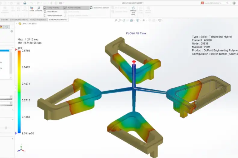
Skipping mold flow analysis can lead to air traps, weld lines, uneven plastic filling, and longer cooling time. Mold flow simulation is essential for defect prevention in molding and cycle time optimization, especially in complex mold insert design or intricate mold halves.
Over-Complicated Mold Design
Excessive complexity in mold building increases tooling cost, maintenance difficulty, and risk of molding defects. Simple, robust designs that follow design for manufacturability (DFM) principles outperform overly complex molds in long-term production.
Poor Communication Between Designer and Toolmaker
Issues often arise when CAD designers lack practical injection molding experience or when molders are consulted too late. Early collaboration ensures proper placement of ejector pins, venting design in molds, and functional mold strength analysis.
Design for Maintenance and Mold Life
Good injection mold design considers long-term operation. Components should be accessible for cleaning, repair, or replacement. Using standard parts where possible, maintaining uniform wall thickness, and designing for part ejection prolong mold life. Production molds are durable assets, and thoughtful design maximizes performance, reduces downtime, and ensures high-quality plastic products throughout the molding process.
Injection Mold Design for High-Volume Production
High-volume molds require careful thermoplastic mold design and robust multi-cavity mold design to produce plastic parts at scale reliably. Key features include:
Hardened tool steel to hold the mold
Hot runner systems to ensure smooth plastic flow as it enters the mold
Automated ejection to ensure the part is ejected cleanly
Design ribs and optimized part geometry when designing your part for strength and dimensional accuracy improvement
Every design decision in high-volume production tooling must support millions of cycles without degradation, maintaining consistent quality and efficiency throughout production while minimizing cycle time and defects.


Prototype vs Production Mold Design
Prototype molds focus on speed, lower cost, and rapid design validation. They often use advanced injection tooling to quickly test concepts and verify part fit, especially for thin-wall molding design or complex part mold design.
Production molds, in contrast, prioritise durability, efficiency, and long-term consistency. High precision tooling design ensures that multi-shot mold design and multi-cavity molds can reliably produce parts at scale with minimal defects.
Confusing prototype and production mold expectations can lead to unrealistic timelines, poor part performance, or costly redesigns. Choosing the right approach ensures your design is validated quickly while the final mold meets the demands of large-scale manufacturing.
The Role of Experience in Injection Mold Design
Software and industry standards are helpful, but experience remains the most important factor in successful injection mold design. Experienced mold designers understand how plastics behave under pressure, how thick areas and large parts fill, and how small adjustments can influence plastic flow and cosmetic appearance.
When the halves of the mold come together, subtle changes in draft angle, gate placement, or wall transitions can determine whether the part may meet tolerances or require rework. Designers with practical experience know which shortcuts fail in production and how the master mold affects consistency across multi-cavity molds. They can also anticipate challenges for parts that require high-precision features or critical surface finishes.
Industries such as automotive mold design, medical device mold design, and consumer product mold engineering rely on experienced injection molders to deliver industrial plastic tooling that produces parts reliably over thousands of cycles. Properly designed molds ensure that the part is ejected cleanly, maintain dimensional accuracy, and provide excellent cosmetic appearance, even for complex or large parts.
Good mold design is not purely theoretical. Understanding how the mold comes together, predicting how the part may behave during ejection, and applying hands-on knowledge are essential. Experienced designers ensure that each molded part is produced efficiently, consistently, and with minimal defects.
Final Thoughts
Injection mold design is not a single step—it is a system-level engineering process that connects product design, material properties, and real-world molding production. Whether you are creating cylindrical parts that require tight tolerances or complex geometries, the mold determines whether the process will deliver consistent, high-quality parts.
A well-executed mold—whether using hardened steel mold design for long-term durability or aluminum mold tooling for rapid prototyping—ensures stable production, lower long-term cost, and faster time to market. Applying sustainable mold design practices also reduces waste and improves efficiency during high-volume runs.
Prototype mold design allows quick validation of concepts and early detection of potential issues, while common injection mold considerations, including flow, cooling, and ejection, must be addressed for production molds. Different design approaches are required depending on the material, part complexity, and production scale.
A poorly designed mold leads to inconsistent parts, increased scrap, and longer lead times. Investing time and expertise in mold design from the outset ensures that your injection molding process is reliable, cost-effective, and capable of producing high-quality parts throughout the life of the mold.
FAQ about injection mold design
1. What is injection mold design?
Injection mold design is the engineering process of creating a mold that shapes molten plastic into finished parts, taking into account part geometry, material behavior, and manufacturing constraints.
2. Why is mold design important for plastic parts?
Good mold design ensures consistent quality, reduces defects, optimizes cycle time, and lowers long-term production costs.
3. What are the main components of an injection mold?
Key components include the mold core and cavity, runner system, gates, cooling channels, ejector pins, and mold base.
4. What is the difference between prototype and production mold design?
Prototype molds focus on speed and cost for testing parts, while production molds prioritize durability, efficiency, and long-term consistency.
5. How does mold design affect part quality?
Design affects wall thickness uniformity, draft angles, gate placement, cooling balance, and venting—all critical for reducing sink marks, warpage, and cosmetic defects.
6. What is a parting line in mold design?
The parting line is where the two halves of the mold meet. Proper placement ensures easier part ejection and minimizes flash or visible defects.
7. What are hot runner and cold runner systems?
Hot runner systems keep plastic molten in the runner for faster cycles and less waste, while cold runner systems are simpler and lower cost but produce more scrap.
8. What is the role of draft angles in mold design?
Draft angles allow the part to release smoothly from the mold halves, preventing drag marks, deformation, and damage to the mold surface.
9. How does cooling channel layout impact injection molding?
Cooling design affects cycle time, part warpage, and dimensional stability. Properly placed channels ensure uniform cooling and efficient production.
10. What materials are commonly considered in mold design?
Thermoplastics like ABS, PP, PC, and high-performance resins are common. Each material has different shrinkage, flow, and temperature characteristics.
11. What is multi-cavity mold design?
Multi-cavity molds produce several identical parts in a single cycle, improving efficiency for high-volume production while requiring precise flow balance.
12. How can mold design reduce defects in molding?
Using proper mold flow analysis, uniform wall thickness, venting, gate placement, and draft angles can prevent sink marks, weld lines, and incomplete filling.
13. What is the difference between aluminum and steel molds?
Aluminum molds are cost-effective and fast for prototypes or short runs, while hardened steel molds are durable and suitable for millions of production cycles.
14. Why is experience important in mold design?
Experienced mold designers understand how plastics behave under pressure, how small changes affect yield, and how to balance manufacturability with cosmetic appearance.
15. How does injection mold design impact production efficiency?
Optimized design improves cycle time, reduces scrap, ensures consistent quality, and allows molds to reliably produce large quantities of parts with minimal maintenance.
Get a quote for your injection mold design
Get a quote for your injection mold design today and discover a reliable solution for producing high-quality, multi-material components. Our experienced team supports custom design, material selection, DFM, mold flow analysis to ensure strength, precision, and cost-effective manufacturing for your injection mold
