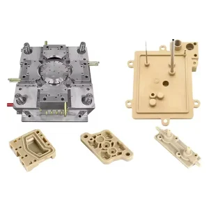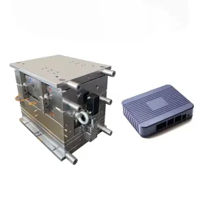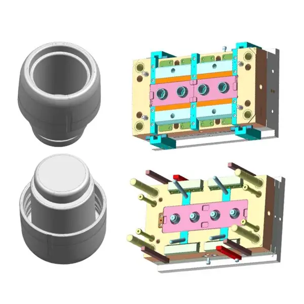
Custom plastic part design for injection molding with AIM plastic, with engineering support, OEM, injection mold making, competitive price, shipment support
Plastic part design for injection molding is where product ideas either succeed smoothly — or become expensive, delayed problems. Many injection molding issues don’t start on the shop floor or the injection molding machine. They start on the CAD screen, long before the first injection mold or prototype is made.
Good plastic part design reduces injection mold cost, improves part quality, shortens lead times, and avoids painful redesigns during the production of plastic parts. Bad part design does the opposite — creating tooling changes, unstable cycles, and surface defects on the plastic parts.
[bg_collapse_level2 view=”link” color=”#e34507″ icon=”arrow” expand_text=”Read More” collapse_text=”Read Less” ]
This guide breaks down part design for injection molding based on real manufacturing constraints, not textbook ideals. Whether you’re designing plastic parts for a prototype, a low-volume run, or high-volume production injection molded parts, these injection molding part design guidelines apply.
Injection molding part design is the process of shaping plastic parts so they can be manufactured reliably, consistently, and economically using an injection molding machine, an injection mold, and a controlled plastic injection molding process.
Unlike general product design, plastic part design for injection must consider how molten thermoplastic behaves inside the mold, including:
Plastic flow and material flow inside the core and cavity
Cooling behaviour and shrinkage control
Mold opening direction and part release
Parting line considerations
Gate location and gate type
Ejection forces and part ejection system design
Material-specific limitations for thermoplastics like polycarbonate, ABS, PP, and nylon
A part that looks perfect in a CAD model or CNC-machined prototype can be impossible — or extremely expensive — to mold if these design considerations are ignored during plastic injection mold design.
Injection molding is a high-precision, repeatable manufacturing process — but it is not forgiving.
Every part design decision directly affects:
Injection mold complexity and cost
Cycle time on the molding machine
Scrap rate and rework
Surface finish and mold surface quality
Dimensional stability and tolerance design for injection molding
Long-term performance of functional parts
Well-designed injection molded parts:
Fill the cavity evenly
Allow balanced plastic flow
Cool uniformly through optimized cooling channel design
Eject cleanly without damaging the surface of the part
Maintain tolerances over long production runs
Poorly designed plastic parts:
Warp due to uneven shrinkage
Show sink marks and surface defects
Flash at the parting line
Short-shot because of poor material flow
Crack under load
Stick to the core during part ejection
Most of these issues are driven by part geometry and plastic part design — not by the injection molding machine itself.
Before discussing geometry, designers must understand how plastic behaves inside the injection mold during the injection molding process.
Molten plastic:
Flows under high pressure from the gate into the cavity
Loses temperature rapidly when contacting the mold surface
Shrinks as it cools and solidifies
Prefers smooth, uniform flow paths
Designs that counteract plastic flow and injection molding flow analysis principles often result in defects.
Key flow realities to consider during the design of plastic parts:
Thin sections fill first, while thick sections cool last
Sharp corners restrict material flow and trap stress
Sudden wall thickness changes cause sink marks and warpage
Long flow lengths increase pressure and stress on the molding machine
Designing with plastic flow — not against it — is the foundation of manufacturability and producing stable, injection-molded parts.
Uniform wall thickness is the single most important rule in plastic part design for injection molding.
Why uniform wall thickness matters:
Even material flow
Consistent cooling across the mold
Controlled shrinkage and warpage control
Reduced internal stress in injection-molded parts
Non-uniform wall thickness leads to:
Sink marks on the surface of the plastic part
Warped parts after ejection
Internal voids
Poor dimensional stability
This principle applies to both prototype molds and full-scale production injection molds.
Typical guidelines for thermoplastics (approximate):
ABS: 1.2–3.5 mm
PP: 1.0–3.0 mm
PE: 1.0–4.0 mm
Polycarbonate: 1.0–3.5 mm
Nylon: 0.8–3.0 mm
Thicker plastic does not automatically mean stronger functional design. Excess thickness often increases cycle time, sink, and shrinkage issues.
If wall thickness changes are unavoidable in part geometry:
Use gradual tapers
Avoid abrupt steps near the core and cavity interface
Core out thick sections instead of making them solid
A practical design for injection molding (DFM) rule:
Wall thickness changes should be less than 30% over a short distance to maintain stable plastic flow.
Draft angle design is essential for plastic part design for injection molding for part release from the injection mold.
Without draft:
Parts stick to the core side of the mold
Surface scratches damage the surface finish
Ejection force increases dramatically
Ejection system wear accelerates
General draft angle design guidelines:
Minimum: 1° per side
Textured mold surfaces: 2–5°
Deep ribs, bosses, or cavities: more draft required
Even small draft angles dramatically improve part ejection, protect the mold surface, and extend mold life.
If appearance concerns lead to “no draft” requests, the engineering reality is simple:
No draft means unstable production of plastic parts.
Ribs are a core feature of injection-molded part geometry in plastic part design for injection molding.
They are used to:
Increase stiffness
Support large flat surfaces
Control warpage
Improve functional design without increasing wall thickness
However, poor rib design for injection molding creates sink marks, stress concentration, and flow imbalance.
Design ribs using these injection molding part design guidelines:
Rib thickness: 40–60% of nominal wall thickness
Rib height: no more than 3× wall thickness
Add draft angle (minimum 0.5–1°)
Use fillets at rib bases to improve material flow
Never design ribs the same thickness as the main wall. That mistake directly causes sink marks on the surface of the part.
Bosses are essential features in plastic part design for injection molding, especially for assembly and product design.
Common uses include:
Screws
Threaded inserts
Structural attachment points
Bosses are also one of the most common failure points in injection-molded parts.
Boss design guidelines for injection molding include:
Core out solid bosses to reduce shrinkage
Keep the boss wall thickness ≤ 60% of the main wall
Connect bosses to ribs for load distribution
Add generous fillets to improve plastic flow
Avoid tall, isolated bosses with thick bases. They cool unevenly, sink into the mold surface, and crack under mechanical load during part ejection or use.
Sharp internal corners are stress concentrators and one of the most common causes of failure in plastic part design for injection molding. Since injection molding is a pressure-driven manufacturing process, sharp corners disrupt polymer flow and weaken structural integrity.
Injection molded parts should always use fillets and radii as part of good mold design and part design technique.
Internal radius ≥ 0.5 × wall thickness
External radius = internal radius + wall thickness
Avoid sharp corners wherever possible, especially near the middle of the part
Proper fillet and radius design improves:
Material flow inside the mold cavity
Plastic part strength optimization
Sink mark prevention
Mold core durability and mold life
Sharp corners may look precise in CAD, but they behave poorly in plastic polymers, especially semi-crystalline materials. Rounded geometry improves moldability, cycle time stability, and overall manufacturing reliability.
Undercuts prevent straight mold opening and complicate injection molding tooling design.
They require additional tool features such as:
Side actions
Lifters
Slides
Collapsible cores
These mold design elements:
Increase mold building complexity
Increase cycle time
Increase failure risk and manufacturing costs
Every undercut should be a conscious design process decision. Ask:
Is the undercut truly required for the function of the molded part?
Can the feature be redesigned using a different design technique?
Can polymer flexibility be used instead of a rigid undercut?
Can the feature be assembled later instead of molded in?
If an undercut is required, design it cleanly, steel safe, and intentionally. Accidental undercuts are one of the fastest ways to destroy moldability and cost-effective mold design.
The parting line is where the mold core and mold cavity meet during mold opening.
Good part design should:
Hide parting lines where possible
Avoid critical sealing or cosmetic surfaces
Allow proper venting design in injection molds
Complex parting lines increase:
Tool complexity
Flash risk
Manufacturing costs
Simple, flat parting lines support cost-effective mold design, easier mold building, and more stable production of plastic parts.
Although gate and sprue design are tooling decisions, part geometry directly limits gate location optimization.
Good injection molding part design:
Allows balanced plastic flow
Supports weld line management
Reduces surface defects on the parts surface
Poor part geometry forces bad gate placement, leading to injection molded part defects.
Designers should understand:
Flow length and thin sections vs thick sections
Fill direction and material flow behaviour
Sensitivity to weld lines
Surface finish requirements and aesthetic priorities
Early DFM discussions between product design engineers and the molder — supported by simulation software — save months of redesign later.
All plastics shrink. Since injection molding relies on cooling the polymer inside a closed mold cavity, shrinkage control is unavoidable in plastic part design for injection molding.
Shrinkage depends on:
Material selection (amorphous vs semi-crystalline polymer)
Wall thickness variation
Flow direction
Cooling rate and mold temperature
Injection molding is not CNC machining.
Typical tolerances:
±0.1–0.2 mm for most manufacturable plastic parts
High-precision plastic parts require higher tooling and process costs
Designers must:
Apply tight tolerances only where the part requires
Allow float in non-critical areas
Understand material behaviour and plastic part dimensional stability
Over-tolerancing is one of the biggest hidden drivers of manufacturing costs in injection molded parts.
Every injection molded part must be ejected from the mold reliably, every cycle.
Design considerations include:
Flat surfaces need proper ejector pin placement
Thin-wall injection molding design requires balanced ejection forces
Textured surfaces require more draft angle and careful ejector design
Avoid:
Large flat areas without support ribs
Deep pockets without sufficient draft
Cosmetic surfaces on the ejection side of the mold
Difficult ejection stops production. Poor ejection system design increases cycle time and damages parts.
Surface finish directly affects part release, appearance, and mold design requirements. We should pay attention to this point in the plastic part design for injection molding.
Surface finish affects:
Ejection behaviour
Draft angle requirements
Manufacturing costs
High-gloss surfaces:
Reveal flow lines and weld lines
Require superior mold polishing
Increase tooling and cycle time
Textured surfaces:
Hide defects
Require additional draft
Improve grip and usability
Surface finish requirements should be defined early in the design process, not after mold design is complete.
Not all plastics behave the same during the injection molding process, so we should consider this part in plastic part design for injection molding.
Design must account for:
Shrinkage rate
Flow length capability
Flexibility and stiffness
Heat and chemical resistance
Examples:
Nylon requires thicker ribs due to high shrinkage
PP tolerates snap-fit design and living hinge design
Polycarbonate needs generous radii to avoid stress cracking
Material selection and plastic part design are inseparable. Poor material-design pairing destroys moldability and long-term performance.
Snap-fit design for plastics reduces assembly cost and eliminates fasteners.
Effective snap-fit design requires:
Flexible polymer materials
Proper engagement and release angles
Controlled stress zones
Key design tips:
Avoid sharp corners in snap arms
Design for repeated assembly if required
Validate designs with prototype injection molding design
Snap fits often fail when designers ignore material behaviour or stress concentration.
These mistakes appear repeatedly in plastic part design for injection molding:
Zero draft angle
Excessive wall thickness
Solid bosses instead of cored geometry
Sharp internal corners
Unnecessary undercuts
Unrealistic tolerances
Ignoring shrinkage and material flow
Most issues are preventable with early DFM and injection molding part design guidelines.
The best injection-molded parts result from early collaboration in plastic part design for injection molding.
DFM review should occur:
Before CAD release
Before the mold quotation
Before material lock-in
A complete DFM review evaluates:
Wall thickness optimization
Draft angle design
Undercut design solutions
Gate options and mold cavity filling
Ejection system design
Tolerance stack-ups and moldability
Skipping DFM does not save time — it delays overall manufacturing.
Prototype injection molding design often allows compromise.
Use aluminium tooling
Accept cosmetic defects
Focus on speed
Production molds:
Require optimized geometry
Support multi-cavity mold design
Demand long-term dimensional stability
Justify higher tooling investment
Design optimization for mass production requires evolving beyond prototype-level geometry.
Before releasing your plastic part design for injection molding, verify:
Uniform wall thickness
Adequate draft on all vertical faces
Correct structural rib placement
Fillet and radius design applied throughout
Undercuts reviewed and justified
Realistic tolerances applied
Material behaviour fully considered
If these checks pass, the part is likely manufacturable and production-ready.
Since injection molding is unforgiving, it rewards disciplined engineering and punishes assumptions.
A few hours spent refining geometry can:
Prevent tooling changes
Reduce cycle time
Improve part quality
Protect mold life
Speed up time to market
Plastic part design for injection molding is not artistic freedom.
It is an engineering discipline, material understanding, and manufacturing reality.
Design with the mold in mind — and stable production will follow.
[/bg_collapse_level2]