
Injection mold tooling and fabrication sit at the core of modern plastic manufacturing. No matter how advanced the injection molding machine or how carefully chosen the plastic material, the quality of the mold ultimately determines part accuracy, surface finish, consistency, and production efficiency.
From concept and design to machining, assembly, testing, and long-term maintenance, injection mold tooling is a complex, highly technical process that demands precision, experience, and close collaboration between designers, toolmakers, and molding engineers.
This end-to-end guide walks through every stage of injection mold tooling and fabrication, explaining best practices, tooling types, materials, cost factors, common challenges, and how to ensure a successful mold project from start to finish.
What Is Injection Mold Tooling?
Injection mold tooling refers to the design, fabrication, assembly, and validation of molds used in the plastic injection molding process. These molds shape molten plastic into finished parts by injecting material into precisely machined cavities under controlled pressure and temperature.
A complete injection mold typically includes:
- Mold base (A-side and B-side)
- Core and cavity inserts
- Runner and gate system
- Cooling channels
- Ejection system
- Venting structures
- Alignment and support components
Well-designed tooling ensures dimensional accuracy, repeatability, and long mold life, even in high-volume production environments.

Why Injection Mold Tooling Is Critical to Product Success
Tooling is often the largest upfront investment in an injection molding project. More importantly, design decisions made during tooling development directly affect:
- Part quality and tolerance
- Cycle time and productivity
- Scrap and defect rates
- Maintenance frequency
- Total cost per part
Poor tooling design can lead to chronic issues such as warpage, sink marks, short shots, flash, or premature tool failure. Conversely, optimized tooling delivers stable, efficient, and scalable production.
Stage 1: Product Design and DFM Analysis
The tooling process begins long before metal is cut.
Part Design Review
Engineers first review the part’s CAD model to evaluate:
- Wall thickness uniformity
- Draft angles
- Undercuts
- Rib and boss design
- Sharp corners and stress points
- Surface finish requirements
Designs that ignore tooling constraints often result in expensive modifications later.
Design for Manufacturability (DFM)
DFM analysis is a critical step that aligns product design with injection molding realities. Key objectives include:
- Reducing mold complexity
- Eliminating unnecessary side actions
- Improving part ejection
- Enhancing material flow
DFM feedback often leads to minor geometry changes that significantly reduce tooling cost and lead time.
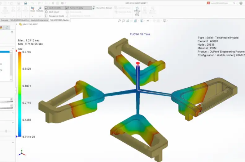
Stage 2: Mold Flow Analysis and Simulation
Before fabrication begins, many projects undergo mold flow simulation to predict how molten plastic will behave inside the mold.
Benefits of Mold Flow Analysis
- Optimizes gate location
- Predicts weld lines and air traps
- Evaluates pressure and temperature distribution
- Reduces warpage and shrinkage risks
- Improves cycle time planning
For complex or high-precision parts, simulation can prevent costly trial-and-error during mold testing.
Stage 3: Mold Design Engineering
Once the part design is finalized, engineers begin detailed mold design.
Core Mold Design Elements
Cavity and Core Design
The cavity defines the outer surface of the part, while the core shapes internal features. Precision machining is essential to maintain tight tolerances.
Runner System Design
The runner system delivers molten plastic to the cavity. Options include:
- Cold runners
- Hot runners
- Valve gate systems
Hot runners reduce material waste but increase tooling complexity and cost.
Gate Design
Gate type and location affect part appearance, strength, and flow behavior. Common gate types include:
- Edge gates
- Fan gates
- Submarine (tunnel) gates
- Pin gates
Cooling System Design
Efficient cooling accounts for up to 70% of the total cycle time. Well-designed cooling channels:
- Reduce cycle time
- Improve dimensional stability
- Minimize warpage
Advanced molds may use conformal cooling for better thermal control.
Ejection System Design
The ejection system removes the part without damage. Options include:
- Ejector pins
- Sleeve ejectors
- Stripper plates
- Air ejection
Improper ejection design leads to part deformation or cosmetic defects.
Stage 4: Tool Steel and Mold Material Selection
Choosing the right mold material is critical for durability and performance.
Common Mold Steels
- P20 Steel – Pre-hardened, cost-effective, widely used
- H13 Steel – High hardness, excellent wear resistance
- S136 / 420 Stainless Steel – Corrosion resistance and high polish
- NAK80 – Excellent machinability and surface finish
Aluminum Molds
Aluminum is often used for prototype or short-run tooling due to:
- Low cost
- Fast machining
- Excellent thermal conductivity
However, aluminum molds have a limited lifespan compared to steel.
Stage 5: CNC Machining and EDM Fabrication
After mold design approval, fabrication begins.
CNC Machining
CNC milling and turning are used to shape:
- Mold bases
- Core and cavity inserts
- Plates and components
High-speed CNC machining ensures accuracy and repeatability.
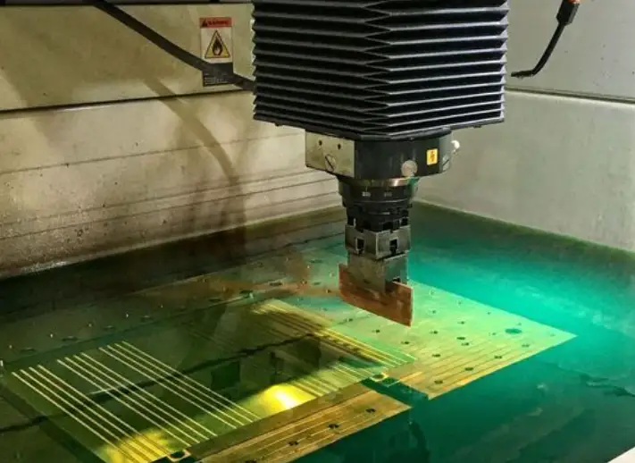
Electrical Discharge Machining (EDM)
EDM is used for:
- Sharp internal corners
- Deep ribs
- Fine details
Wire EDM and sinker EDM allow complex geometries that are difficult to machine conventionally.
Stage 6: Mold Assembly and Fitting
After machining, components are assembled and hand-fitted.
Key Assembly Tasks
- Installing ejector systems
- Aligning cores and cavities
- Polishing parting surfaces
- Checking tolerances and clearances
Skilled toolmakers perform fine adjustments to ensure smooth operation and perfect sealing.
Stage 7: Mold Polishing and Surface Finishing
Surface finish directly impacts part appearance and release.
Common Mold Finishes
- SPI A-1 (mirror polish)
- SPI B-2 (semi-gloss)
- SPI C-1 (matte)
- Textured finishes (MT, VDI)
The required finish depends on part function, aesthetics, and material choice.
Stage 8: Mold Testing and Trial (T1, T2, T3)
Before mass production, molds undergo multiple trial runs.
Mold Trial Objectives
- Validate part dimensions
- Optimize process parameters
- Identify defects
- Confirm cycle time
Issues found during T1 trials are corrected before further testing.
Stage 9: Mold Modification and Optimization
Rarely does a mold go into production without adjustments.
Common modifications include:
- Gate resizing
- Venting improvements
- Cooling channel enhancement
- Ejection system tuning
This optimization phase ensures stable, repeatable production.
Stage 10: Production Release and Documentation
Once approved, the mold is released for production.
Documentation Includes
- Mold drawings
- Maintenance schedules
- Process parameters
- Material specifications
Proper documentation ensures consistent results across production runs.
Mold Maintenance and Lifecycle Management
Injection molds require ongoing maintenance to maintain performance.
Preventive Maintenance Tasks
- Cleaning vents and runners
- Lubricating moving components
- Inspecting wear areas
- Polishing parting lines
Regular maintenance extends mold life and prevents unexpected downtime.
Injection Mold Tooling Cost Factors
Tooling cost depends on:
- Part size and complexity
- Number of cavities
- Mold material
- Tolerance requirements
- Hot runner systems
- Surface finish
While high-quality tooling costs more upfront, it significantly reduces long-term production costs.
Common Challenges in Injection Mold Tooling
- Poor DFM communication
- Inadequate cooling design
- Material mismatch
- Over-engineering
- Insufficient testing
Early collaboration between all stakeholders is the best way to avoid these issues.
Choosing the Right Injection Mold Tooling Partner
A reliable tooling partner should offer:
- In-house mold design and fabrication
- DFM and mold flow support
- Transparent pricing
- Clear project timelines
- Long-term maintenance support
Experience and communication matter as much as machining capability.
Future Trends in Injection Mold Tooling
- Conformal cooling via additive manufacturing
- Smart molds with sensors
- Faster tooling for short-run production
- Automation and digital twins
These innovations continue to improve efficiency and part quality.
Conclusion
Injection mold tooling and fabrication is a multi-stage, precision-driven process that defines the success of any injection molding project. From early DFM analysis to final production release, every decision impacts cost, quality, and scalability.
By understanding the end-to-end tooling process and working with experienced tooling partners, manufacturers can reduce risk, accelerate time-to-market, and achieve consistent, high-quality plastic parts.
A well-designed mold is not just a tool—it is a long-term manufacturing asset.