
Injection molding is one of the most widely used manufacturing processes in modern industry. From automotive components and electronic housings to medical devices and consumer products, injection molding provides high-volume, repeatable, and cost-effective production. However, achieving precision in molded parts is a challenge, and tolerances play a critical role in ensuring consistent quality.
Injection molding tolerances determine how much a part can deviate from its nominal dimensions without impacting functionality. Understanding these tolerances, how to design for them, and how to control them during production is essential for engineers, designers, and manufacturers aiming to produce high-quality, reliable parts.
In this guide, we’ll explore what injection molding tolerances are, why they matter, factors affecting tolerances, design considerations, measurement methods, and best practices for achieving precision in your parts.
What Are Injection Molding Tolerances?
In engineering, a tolerance is the permissible limit of variation in a part’s dimensions. For injection molded components, tolerances define how much a feature, such as a hole, wall thickness, or external dimension, can vary from the nominal specification.
- Tight tolerance: Minimal deviation allowed. Usually critical for interfacing parts or mechanical assemblies.
- Loose tolerance: Greater allowable deviation. Typically acceptable for non-critical or cosmetic features.
For example, if a shaft is designed to be 10 mm in diameter with a tolerance of ±0.05 mm, the actual manufactured shaft can range from 9.95 mm to 10.05 mm.

Why Injection Molding Tolerances Matter
Injection molding tolerances directly affect:
- Part Fit and Function
Critical dimensions must meet design requirements to ensure proper assembly. Misalignment can cause mechanical failure or improper mating with other components. - Interchangeability
For mass production, parts must be interchangeable without additional finishing or adjustment. - Aesthetic Quality
Even small deviations in cosmetic features like panels, logos, or edges can affect visual appearance and brand perception. - Material Performance
Incorrect wall thickness or dimensions may lead to warpage, sink marks, or internal stress, affecting mechanical properties. - Cost Efficiency
Tight tolerances increase tooling costs and cycle times. Balancing precision and cost is key to economical manufacturing.
Standard Injection Molding Tolerances
There is no universal tolerance standard for all injection-molded parts, but general guidelines exist. Tolerances are influenced by:
- Part size
- Wall thickness
- Material type
- Machine precision
Typical Tolerance Ranges
| Feature Type | Typical Tolerance |
|---|---|
| Small features (<25 mm) | ±0.05 mm |
| Medium features (25–100 mm) | ±0.1 mm |
| Large features (>100 mm) | ±0.15–0.25 mm |
| Holes, slots | ±0.05–0.1 mm |
| Wall thickness | ±0.05–0.2 mm |
| Overall dimensions | ±0.1–0.25 mm |
Note: Tolerances vary depending on material, mould design, and processing capabilities. Engineering plastics like PC or PEEK may require tighter control compared to commodity plastics like PP or PE.
Factors Affecting Injection Molding Tolerances
Achieving tight tolerances in injection molding depends on material properties, design, tooling, and process parameters. Let’s explore each factor.
1. Material Properties
Different plastics shrink and flow differently, impacting final dimensions.
- Thermal shrinkage: Plastics contract as they cool. Engineering plastics like Nylon or Polycarbonate shrink more than PP or ABS.
- Hygroscopic behavior: Materials like Nylon absorb moisture, causing dimensional changes.
- Viscosity: High-viscosity resins may not fill thin or complex sections uniformly.
Tip: Consult manufacturer datasheets for shrinkage rates and adjust mould design accordingly.

2. Part Design
Good design reduces dimensional variability.
- Uniform wall thickness: Reduces stress, shrinkage, and warpage.
- Fillets and radii: Avoid sharp corners that can cause sink marks.
- Draft angles: Facilitate ejection and prevent part distortion.
- Ribs and gussets: Provide stiffness without increasing wall thickness excessively.
Rule of Thumb: Design for manufacturability (DFM) with tolerances in mind. Overly tight dimensions may be unnecessary and costly.
3. Tooling Quality
The mould itself is a major determinant of tolerances.
- Precision machining: CNC-milled steel or aluminum moulds with tight tolerances ensure accurate parts.
- Surface finish: Polished or textured surfaces affect cooling and shrinkage.
- Mould wear: Worn tooling can introduce dimensional variability.
- Cooling channels: Uneven cooling leads to warpage and inconsistent dimensions.
Tip: Regular tool maintenance and inspection are essential for consistent tolerances.
4. Process Parameters
Injection molding parameters influence part dimensions and variability.
- Injection pressure and speed: Higher pressure can over-pack the mould, causing flash; too low pressure causes short shots.
- Mould temperature: Affects shrinkage and surface quality. Uniform temperature reduces warpage.
- Cycle time: Insufficient cooling leads to dimensional instability; excessive cooling increases cycle time and cost.
- Screw and barrel settings: Proper plasticizing and consistent melt temperature prevent voids and flow defects.
5. Environmental Factors
- Ambient temperature and humidity can affect moulded parts.
- Moisture in hygroscopic materials may alter dimensions.
- Consistent factory conditions improve repeatability.
Methods to Control Injection Molding Tolerances
Manufacturers employ several methods to ensure precision in injection-molded parts.
1. Material Selection
- Use low-shrinkage plastics for tight-tolerance applications.
- Consider reinforced plastics (glass-filled, carbon fiber) to reduce warpage.
- Pre-dry hygroscopic resins to minimize dimensional changes.
2. Mould Design Optimisation
- Use uniform wall thickness wherever possible.
- Add draft angles for easier ejection.
- Include venting and balanced cooling channels.
- Design gate locations to minimize flow-related defects.
Advanced techniques:
- Hot runner systems: Improve flow and reduce shrinkage at gates.
- Conformal cooling: Provides uniform cooling and reduces warpage.

3. Process Parameter Control
- Monitor injection pressure, speed, and temperature carefully.
- Use machine sensors and SPC (Statistical Process Control) to detect deviations.
- Fine-tune holding pressure and packing time based on part geometry.
Modern machines allow real-time adjustments, ensuring consistent tolerances.
4. Post-Molding Operations
- Annealing: Heat treatment reduces internal stress and improves dimensional stability.
- Trimming and machining: For features requiring ultra-tight tolerances.
- Inspection and feedback: Dimensional measurements guide process adjustments.
Measurement Techniques for Injection Molding Tolerances
Accurate measurement is essential to verify that parts meet specifications.
1. Coordinate Measuring Machines (CMM)
- Provides 3D dimensional inspection with high accuracy.
- Ideal for complex parts and critical dimensions.
2. Optical Comparators
- Uses magnification to compare parts against profiles.
- Suitable for smaller or optical components.
3. Calipers and Micrometers
- Manual measurement for quick checks on simple features.
- Accuracy depends on operator skill.
4. Statistical Process Control (SPC)
- Tracks process variation over time.
- Helps identify trends before parts go out of tolerance.
Common Injection Molding Tolerance Challenges
- Shrinkage Variability – Different sections of the part shrink differently.
- Warpage – Uneven cooling or differential shrinkage.
- Sink Marks – Thick sections cool unevenly, causing surface dimples.
- Flash – Too much injection pressure or worn tooling.
- Short Shots – Incomplete filling due to flow restrictions.
Solution: Proper material selection, design optimisation, and process control mitigate these challenges.
Industry Standards for Injection Molding Tolerances
- ISO 20457: Specifies tolerances for plastic injection molded parts.
- DIN 16901: Standard for general tolerances in plastic components.
- IPC/IEC standards: Relevant for electrical and electronics applications.
Following standards ensures consistency and reduces the risk of parts being rejected in assembly.
Tips for Designing Parts with Tight Tolerances
- Understand functional requirements: Only specify tight tolerances where necessary.
- Minimize thick sections: Reduces warpage and shrinkage.
- Use ribbing instead of thick walls: Maintains strength without affecting dimensions.
- Include proper draft angles: Helps ejection and reduces distortion.
- Balance cavities in multi-cavity molds: Ensures all parts have consistent dimensions.
- Consult mold makers early: They can advise on achievable tolerances.
Advanced Techniques for High-Precision Injection Molding
1. Multi-Shot Molding
- Combines multiple materials or colors in one part.
- Requires careful control of tolerances across different components.
2. Micro-Injection Molding
- Produces small parts with high dimensional accuracy.
- Suitable for medical devices, electronics, and precision components.
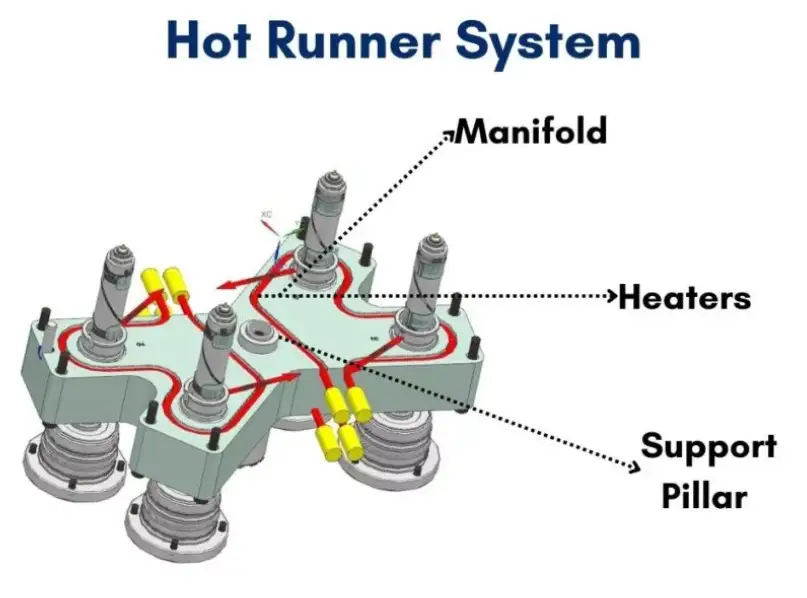
3. Hot Runner Systems
- Maintains molten plastic in the runner, reducing pressure fluctuations.
- Improves part consistency and dimensional accuracy.
4. Automation and AI
- Real-time monitoring adjusts injection parameters automatically.
- Predictive maintenance ensures tooling remains within tolerance specifications.
Case Study: Achieving Tight Tolerances in Automotive Components
Scenario: Manufacturing a 100 mm ABS gear housing with ±0.05 mm tolerance.
Approach:
- Material pre-dried to <0.02% moisture.
- A mold with balanced cooling channels is designed.
- A high-precision electric injection molding machine is used.
- SPC was implemented to monitor cavity pressure and temperature.
- Post-mold annealing is applied to relieve internal stress.
Result: 95% of parts met the ±0.05 mm requirement, reducing scrap and assembly adjustments.
Balancing Cost and Tolerance Requirements
- Tighter tolerances increase tooling cost, machine time, and material handling.
- Overly loose tolerances can compromise part functionality.
- Best practice: Specify tight tolerances only for critical features and relax them elsewhere.
Final Thoughts: Ensuring Precision in Injection Molding
Injection molding tolerances are critical to part quality, functionality, and cost-effectiveness. Achieving precise dimensions requires:
- Selecting the right material
- Optimizing part and mold design
- Controlling process parameters
- Regular maintenance and inspection
By understanding and controlling these factors, manufacturers can produce high-quality, consistent, and reliable injection-molded parts, ensuring that components fit, function, and perform as intended in their applications.