
In modern plastic injection molding, success is no longer driven by experience alone. While skilled engineers and mold makers remain essential, advanced simulation and mold flow analysis have become critical tools for producing better parts, faster development cycles, and lower production risk.
Today’s manufacturers face increasing pressure to deliver lighter parts, tighter tolerances, shorter lead times, and lower costs—often all at once. Relying on trial-and-error mold tuning is no longer efficient or competitive. This is where advanced mold flow simulation transforms the way plastic parts and molds are designed.
This article explores what mold flow analysis is, how advanced simulation works, why it matters, and how it directly improves part quality, tooling reliability, and production efficiency.
What Is Mold Flow Analysis?
Mold flow analysis is a computer-based simulation used to predict how molten plastic will flow, fill, pack, cool, and solidify inside a mold cavity during the injection molding process.
Using advanced software, engineers can simulate:
- Melt flow behavior
- Filling patterns
- Pressure distribution
- Temperature gradients
- Cooling efficiency
- Shrinkage and warpage
- Weld line locations
- Air traps and burn risks
Instead of guessing what might happen in a mold, mold flow analysis shows what will happen—before steel is cut.
Why Advanced Simulation Matters in Injection Molding
Injection molding defects are expensive. A single design mistake can lead to:
- Costly mold rework
- Extended lead times
- High scrap rates
- Poor part quality
- Production instability
Advanced simulation shifts the process from reactive problem-solving to predictive engineering.
Key Benefits of Mold Flow Simulation
- Reduce mold rework and modification
- Improve part quality and consistency
- Optimize cycle time and cooling
- Lower material and energy waste
- Shorten product development cycles
- Improve communication between design, tooling, and production
For complex or high-volume projects, simulation is no longer optional—it’s a competitive necessity.
How Advanced Mold Flow Simulation Works
Mold flow analysis uses finite element analysis (FEA) and computational fluid dynamics (CFD) to simulate real-world molding conditions.
Typical Simulation Workflow
- Import 3D CAD model of the part
- Define material properties (viscosity, shrinkage, thermal behavior)
- Set process parameters (temperature, injection speed, pressure)
- Design gating and runner systems
- Simulate filling, packing, cooling, and warpage
- Analyze results and optimize design
- Validate the final mold design before manufacturing
Each stage reveals potential issues that would otherwise appear after the mold is built.
Key Areas Where Mold Flow Analysis Improves Parts
1. Filling Analysis: Ensuring Complete and Balanced Flow
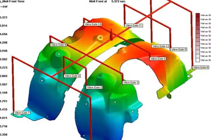
Filling simulation predicts how molten plastic flows through the cavity.
It helps identify:
- Short shots
- Flow hesitation
- Unbalanced filling in multi-cavity molds
- Excessive shear stress
Why This Matters
Poor filling causes:
- Incomplete parts
- Weak weld lines
- Surface defects
- Dimensional inconsistency
Simulation allows engineers to:
- Adjust gate size and location
- Optimize injection speed
- Select higher-flow materials
- Balance runner systems
2. Gate Location Optimization
Gate placement has a major impact on part quality.

Mold flow analysis evaluates:
- Flow length
- Pressure drop
- Weld line position
- Cosmetic impact
Simulation Helps Answer:
- Where should the gate be placed?
- Should a single gate or multiple gates be used?
- What gate type works best?
Optimized gating improves strength, appearance, and dimensional stability.
3. Weld Line Prediction and Control
Weld lines form where two melt fronts meet. They are often unavoidable—but they can be controlled.
Simulation predicts:
- Weld line locations
- Weld line strength
- Visual impact
This allows designers to:
- Move weld lines away from stress points
- Adjust gate position
- Modify wall thickness
- Improve part durability
For automotive, medical, and structural parts, weld line control is critical.
4. Air Trap and Burn Mark Detection
Trapped air causes:
- Burn marks
- Incomplete filling
- Weak spots
Advanced simulation identifies:
- Air trap locations
- Venting requirements
- Areas at risk of gas compression
This enables:
- Proper vent placement
- Improved surface quality
- Reduced scrap rate
5. Packing and Holding Pressure Optimization
Packing pressure compensates for shrinkage as plastic cools.
Mold flow simulation analyzes:
- Pressure distribution
- Volumetric shrinkage
- Sink mark risk
With proper packing simulation, engineers can:
- Reduce sink marks
- Improve dimensional accuracy
- Minimize internal stress
6. Cooling Analysis: Reducing Cycle Time and Warpage
Cooling often accounts for 50–70% of total cycle time.
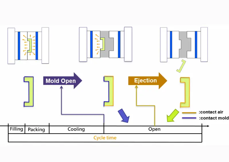
Advanced cooling simulation evaluates:
- Cooling channel layout
- Heat transfer efficiency
- Temperature uniformity
Benefits of Cooling Simulation
- Shorter cycle times
- Reduced warpage
- Improved surface finish
- Extended mold life
Simulation also supports conformal cooling design, especially for complex parts.
7. Warpage and Shrinkage Prediction
Warpage is one of the most costly injection molding defects.
Simulation predicts:
- Direction and magnitude of warpage
- Differential shrinkage
- Stress concentration areas
Engineers can then:
- Adjust wall thickness
- Modify rib design
- Balance cooling
- Change material selection
This prevents costly mold rework after production starts.
Advanced Simulation vs Traditional Trial-and-Error
| Aspect | Trial-and-Error | Advanced Simulation |
|---|---|---|
| Development Time | Long | Short |
| Mold Rework | Frequent | Minimal |
| Cost Control | Poor | Predictable |
| Quality Consistency | Variable | High |
| Risk Level | High | Low |
Simulation replaces guesswork with data-driven decisions.
Materials and Mold Flow Simulation
Different plastics behave very differently in a mold.
Simulation accounts for:
- Viscosity vs temperature
- Shear sensitivity
- Shrinkage rate
- Fiber orientation (for reinforced plastics)
Common Materials Simulated
- PP, PE, PS
- ABS
- Polycarbonate (PC)
- Nylon (PA6, PA66)
- Glass-filled materials
- High-performance plastics (PEEK, PPS)
This allows precise process tuning for each material.

Mold Flow Analysis for Thin-Wall Injection Molding
Thin-wall parts are especially challenging.
Simulation helps by:
- Predicting flow length limits
- Optimizing injection speed
- Reducing pressure drop
- Preventing short shots
Without simulation, thin-wall molding often relies on costly experimentation.
Multi-Cavity and Family Mold Simulation
In multi-cavity molds, imbalance causes:
- Dimensional variation
- Weight differences
- Uneven cooling
Advanced simulation balances:
- Runner diameters
- Flow resistance
- Filling time
This ensures all cavities produce identical parts, critical for high-volume production.
Mold Flow Analysis for Fiber-Filled Plastics
Glass- or carbon-filled materials introduce additional complexity.
Simulation predicts:
- Fiber orientation
- Anisotropic shrinkage
- Strength directionality
This is essential for:
- Structural components
- Load-bearing parts
- Automotive and industrial applications
Incorrect fiber orientation can cause premature failure.
Simulation in Early Product Design (DFM)
The greatest value of mold flow analysis comes early in the design phase.
Early simulation helps:
- Avoid un-moldable designs
- Reduce unnecessary tight tolerances
- Optimize wall thickness
- Simplify tooling
This aligns perfectly with Design for Manufacturability (DFM) principles.
Cost Savings from Advanced Mold Flow Simulation
Although simulation adds upfront cost, it saves significantly more downstream.
Cost Reduction Areas
- Fewer mold modifications
- Shorter time-to-market
- Reduced scrap rate
- Lower energy consumption
- More stable production
For complex molds, simulation often pays for itself before the first production run.
Integration with Modern Injection Molding Technology
Advanced simulation integrates with:
- Electric and hybrid injection molding machines
- Real-time process monitoring
- Industry 4.0 systems
- Digital twins
Simulation data can be used to:
- Set initial machine parameters
- Reduce startup scrap
- Improve first-shot success rate
Common Mistakes When Using Mold Flow Analysis
- Using incorrect material data
- Ignoring simulation results
- Running the simulation too late
- Over-relying on software without engineering judgment
- Not updating the simulation after design changes
Simulation is a tool—not a replacement for experience.
Industries That Benefit Most from Mold Flow Simulation
Automotive
- Structural parts
- Thin-wall components
- Fiber-reinforced materials
Medical
- Tight tolerances
- Thin sections
- High reliability
Electronics
- Cosmetic surfaces
- Precision housings
- Heat-sensitive materials
Packaging
- Thin-wall containers
- High-speed production
- Cost optimization
Future Trends in Mold Flow Simulation
The field continues to evolve rapidly.
Key Trends
- AI-assisted simulation
- Faster cloud-based analysis
- Real-time digital twins
- Improved fiber orientation modeling
- Better prediction of surface defects
Simulation is becoming faster, more accurate, and more accessible.
Final Thoughts: Better Parts Start with Better Simulation
Advanced simulation and mold flow analysis have fundamentally changed injection molding.
They enable manufacturers to:
- Predict problems before they happen
- Design better parts
- Build better molds
- Run a more stable production
- Reduce cost and risk
In today’s competitive manufacturing environment, companies that use simulation effectively gain a clear technical and commercial advantage.
Better parts don’t happen by accident—they are engineered, simulated, and optimized from the start.