
Injection molding machines are the backbone of modern plastic manufacturing. From everyday household products to high-precision automotive and medical components, these machines enable the mass production of consistent, complex plastic parts with remarkable efficiency.
While injection molding may appear simple from the outside—plastic goes in, parts come out—the internal process is highly controlled and technically sophisticated. Each stage, from clamping the mold to ejecting the finished part, plays a critical role in part quality, cycle time, and production stability.
This article provides a complete, step-by-step explanation of how injection molding machines work, breaking down the structure, operating principles, and each phase of the molding cycle in practical, easy-to-understand terms.
What Is an Injection Molding Machine?
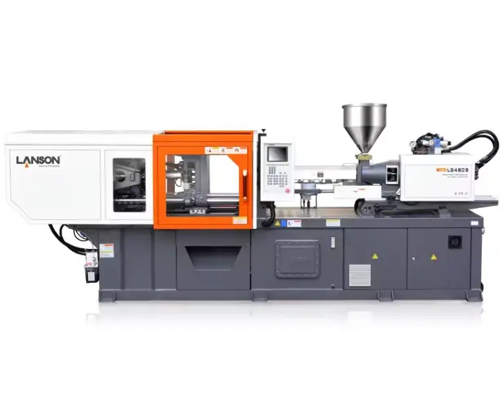
An injection molding machine is an industrial system designed to melt plastic material, inject it into a mold cavity under pressure, allow it to cool and solidify, and then eject the finished part.
The machine integrates mechanical, hydraulic, electrical, and thermal systems to achieve precise control over pressure, temperature, speed, and timing.
Injection molding machines are widely used for producing parts made from thermoplastics such as ABS, polypropylene, polyethylene, polycarbonate, nylon, and many engineering plastics.
Main Components of an Injection Molding Machine
To understand how injection molding machines work, it is essential to understand their core components.
Clamping Unit
The clamping unit holds the mold closed during injection and cooling. It must generate sufficient force to counteract the high pressure of molten plastic entering the mold.
Key elements include:
- Fixed platen
- Moving platen
- Tie bars
- Clamping mechanism (toggle or hydraulic)
Injection Unit
The injection unit is responsible for melting, mixing, and injecting the plastic material into the mold.
It consists of:
- Hopper
- Heated barrel
- Reciprocating screw
- Nozzle
Control System
The control system manages:
- Injection speed and pressure
- Temperature zones
- Clamp force
- Cycle timing
Modern machines use advanced PLC or servo control systems for accuracy and repeatability.
Hydraulic or Electric Drive System
Injection molding machines can be:
- Hydraulic
- Electric
- Hybrid
Each system provides power to the clamping and injection units.
Types of Injection Molding Machines
Hydraulic Injection Molding Machines
Hydraulic machines use oil-driven systems to generate force.
Advantages:
- High clamping force
- Robust and durable
- Suitable for large parts
Limitations:
- Higher energy consumption
- Noise and oil maintenance
Electric Injection Molding Machines
Electric machines use servo motors for all movements.
Advantages:
- High precision
- Energy efficient
- Clean operation
Limitations:
- Higher initial cost
- Limited for extremely large molds
Hybrid Injection Molding Machines
Hybrid machines combine hydraulic power with electric precision, offering a balance between performance and efficiency.

The Injection Molding Cycle: Step-by-Step
The operation of an injection molding machine follows a repeatable cycle. Each phase must be precisely controlled.
Step 1: Mold Clamping
The cycle begins with mold clamping.
How Clamping Works
- The moving platen closes the mold against the fixed platen
- The clamping system applies force to keep the mold tightly closed
- Clamp force must exceed the internal cavity pressure
If the clamp force is insufficient, flash occurs.
Clamping Mechanisms
- Toggle clamping: Mechanical amplification, energy efficient
- Hydraulic clamping: Direct pressure control, flexible
Clamping is critical for dimensional accuracy and surface quality.
Step 2: Plasticising (Melting the Material)
While the mold is clamped, the injection unit prepares the molten plastic.
Plasticising Process
- Plastic pellets enter the barrel through the hopper
- Heater bands raise the barrel temperature
- The rotating screw conveys, compresses, and melts the material
Friction and shear generated by screw rotation contribute significantly to melting.
Screw Design and Function
The screw typically has three zones:
- Feed zone
- Compression zone
- Metering zone
Proper screw design ensures uniform melt temperature and consistency.
Step 3: Injection (Filling the Mold)
Once sufficient molten material is prepared, the injection phase begins.
Injection Movement
- The screw moves forward like a plunger
- Molten plastic is forced through the nozzle and runner system
- Plastic fills the mold cavity at a controlled speed and pressure
Injection parameters directly affect:
- Flow pattern
- Weld lines
- Surface finish
Injection Speed and Pressure Control
- High speed reduces weld lines but increases shear
- Low speed improves surface quality but may cause short shots
Balancing speed and pressure is essential.
Step 4: Packing and Holding Pressure
After the cavity is filled, the machine switches to packing and holding.
Purpose of Packing
- Compensate for material shrinkage
- Improve part density
- Reduce sink marks and voids
Holding pressure is maintained until the gate freezes.
Step 5: Cooling and Solidification
Cooling begins as soon as the plastic contacts the mold.
Role of Cooling
- Solidifies the plastic
- Defines final part dimensions
- Controls cycle time
Cooling typically represents 60–70% of total cycle time.
Efficient cooling system design improves productivity and reduces warpage.
Step 6: Screw Recovery
While the part cools, the screw rotates again to prepare material for the next cycle.
This overlapping action improves overall cycle efficiency.
Step 7: Mold Opening
After sufficient cooling time:
- The clamping unit releases force
- The moving platen opens the mold
Opening speed is controlled to avoid part sticking or damage.
Step 8: Ejection
Ejection is the final stage of the cycle.
Ejection System Operation
- Ejector pins, sleeves, or plates push the part out
- Ejection force must overcome part adhesion and friction
Proper ejection design prevents deformation and surface marks.
Types of Ejection Systems
- Pin ejection
- Sleeve ejection
- Stripper plate
- Air ejection
Parts must eject cleanly and consistently to maintain automation.
Key Process Parameters That Control Machine Operation
Injection molding machines rely on precise parameter control.
Key parameters include:
- Barrel temperature
- Injection speed
- Injection pressure
- Clamp force
- Cooling time
- Screw speed
Small parameter changes can significantly affect part quality.
Common Problems Related to Machine Operation
Machine settings and injection molding machine performance play a critical role in part quality. Many molding defects are directly linked to improper machine operation rather than mold design alone.
Short Shots
Short shots occur when the mold cavity is not filled.
Typical machine-related causes include:
Low injection pressure or injection speed
Insufficient melt temperature reduces plastic flow
Inadequate screw recovery or shot size
Improper plasticising can prevent the molten material from reaching all areas of the mold before solidification.
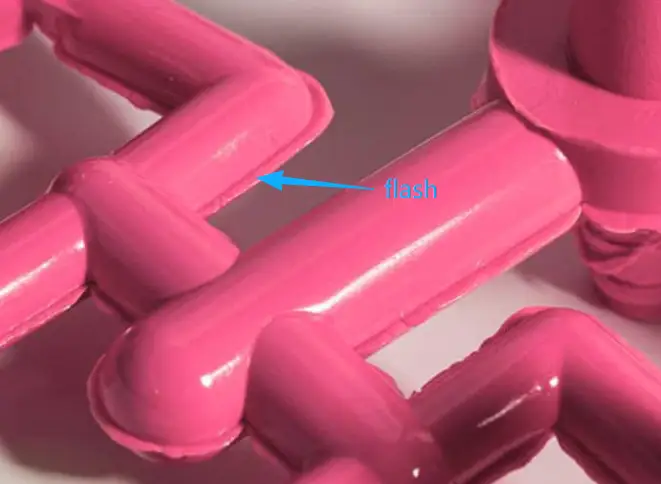
Flash
Flash is excess material that escapes from the mold cavity.
Common machine causes include:
Insufficient clamp force allows the mold to open during injection
Excessive injection or packing pressure
Machine wear leading to poor platen alignment
An incorrect clamping setup becomes more critical in high-pressure molding conditions.
Burn Marks
Burn marks appear as dark or scorched areas on the part surface.
Primary causes include:
Trapped air compressed during injection
Poor venting combined with high injection speed
Overheating due to excessive shear
Warpage
Warpage results in part distortion after ejection.
Machine-related factors include:
Uneven cooling due to inconsistent mold temperature control
Incorrect packing pressure or holding time
Understanding machine operation and parameter interaction helps identify root causes and achieve stable, repeatable molding results.
Automation and Modern Injection Molding Machines
Modern machines integrate automation, such as:
- Robotic part removal
- Vision inspection
- Closed-loop control systems
Smart machines improve:
- Consistency
- Traceability
- Production efficiency
Energy Efficiency and Sustainability
Injection molding machines have evolved to reduce energy consumption.
Key improvements include:
- Servo-driven systems
- Optimised heating zones
- Reduced idle power usage
Energy-efficient machines lower operating costs and carbon footprint.
Safety Considerations
Injection molding machines operate under:
- High pressure
- High temperature
- Heavy mechanical loads
Safety systems include:
- Interlocked guards
- Emergency stops
- Pressure monitoring
Operator training is essential for safe operation.
Injection Molding Machines in Different Industries
Injection molding machines support a wide range of industries:
- Automotive
- Electronics
- Medical
- Packaging
- Industrial equipment
Machine size, configuration, and precision vary by application.
Final Thoughts
Understanding how injection molding machines work—from clamping to ejection—provides valuable insight into the entire plastic manufacturing process.
This knowledge helps:
- Improve part design
- Optimise process parameters
- Reduce defects
- Increase production efficiency
Injection molding is not just about machines or molds—it is about how all elements work together in a controlled, repeatable system.
Mastering machine operation is a critical step toward achieving stable, high-quality injection molding production.